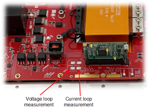
5.10 Control Loop Measurement
The control loop is implemented through two cascaded loops. An outer voltage loop generates the current reference for an inner current loop, which is an implementation of Average Current mode control. This inner current loop then generates the required phase-shift to achieve the output voltage set point.