
5.10.2 Voltage Loop Measurement for Single Rail Operation
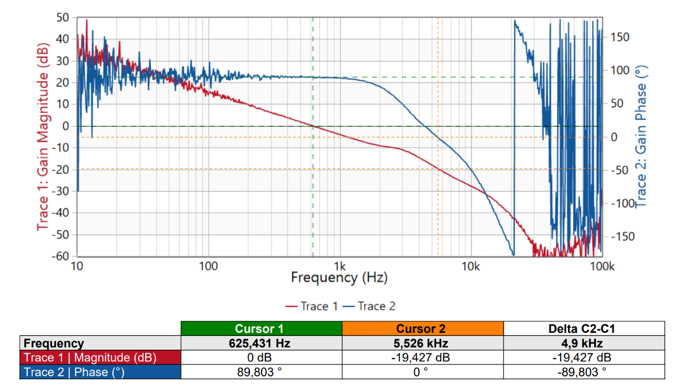 Test conditions: VIN = 800V, VOUT = 12V, IOUT = 80A Results:Phase margin = 90⁰ Gain margin = -19.4dB Crossover frequency = 625Hz Crossover slope = -20dB/decade |
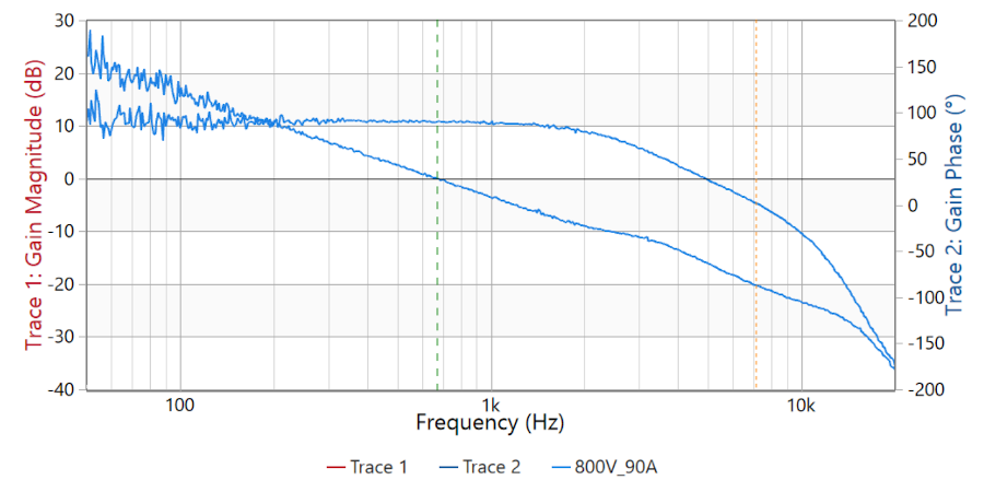 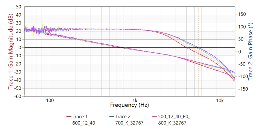 Observations: At different input voltage from 500V to 800V, plant gain variation is very small due to the transformer turns to ratio (17:01), therefore, an AGC (Adaptive gain control) is not required. |