
Virtual Target Write Transfers
The Virtual Target write transfers use the same Controller write transfer flow. The shared peripheral logic accepts the write address (ACK response) when the following conditions are met:
- The Receive Buffer has space (in terms of empty locations) equal to or more than the programmed value of the I3C1BUFTHLD [RXSTART].
- The Response Queue is not full, and it has some space to hold the first response for the current write transfer. Otherwise, the shared peripheral logic responds with a NACK response for the write transfer and ignores the write transfer.
Once the write address is acknowledged with ACK (accepted), the Target expects the RX FIFO space to be available until the end of the transfer to avoid an overflow condition. In the non-DMA mode of operation, use either the I3C1INTSTA[RXTHLDSTA] interrupt to free up the RX FIFO space while the RX data is being received, or configure the RX FIFO to accommodate the entire write transfer data (when the maximum write transfer size is defined and small). In the DMA mode of operation, the DMA request of the handshake interface is initiated when the RX FIFO level reaches the programmed I3C1BUFTHLD[RXBUF] level.
When an overflow condition is encountered (when the system latency is too high to consume the receiving data), the Target sets the I3CxCLTCCCSTAT [OVFLWERR] bit of the register and drops the further incoming data until the termination (either STOP or RESTART) is detected.
When a parity error is encountered during the write transfer, the Shared Peripheral Logic sets the I3CxCLTCCCSTAT [PROTOERR] bit of the register and drops the further incoming data until the termination is detected.
Once the Shared Peripheral Logic sets the overflow error or protocol error bit, it rejects (NACK) any further private or Vendor Specific CCC transfer requests from the Controller until the Controller reads the Target status through a GETSTATUS CCC and the Target application resumes the Target operation by setting the bit I3CxCNTRL [RESUME].
If the receive FIFO does not have a threshold amount of space to accommodate the write transfer, the Controller NACKs the request and the I3CxCLTCCCSTAT [BUFFNTAVAIL] bit is set. Once the buffer not available bit is set, it rejects (NACKs) any further private write transfer requests from the Controller until space is available in the receive FIFO. As the broadcast CCCs do not have any mechanism to NACK the incoming data, the incoming broadcast CCC is not sent to the user application.
The response FIFO full condition is met during a transfer, and if another response has to be generated during the response FIFO full condition, the overflow error is asserted and data is lost after this point. This behavior is similar to the data FIFO overflow during the transfer. Response FIFO overflow recovery is treated similarly to data FIFO overflow recovery.
The frequency of the responses for the write transfer is controlled by the threshold I3CxECRTCON [RSPDATTHLD]. It indicates after how many data bytes a new transfer is generated. For the last response of the transfer, the indicated data length is less than or equal to the threshold I3CxECRTCON [RSPDATTHLD].
The Shared Peripheral Logic includes the following in the generated response (retrieved from the response queue) for the write transfer:
- DATA_LENGTH: Reports the data length of the transfer or part of the transfer that the response represents. If DEFTGTS == 0, or if DEFTGTS == 1, it represents the device count byte for DEFTGTS CCC.
- Target_ID: Reports the Virtual Target/Targets that this transfer is intended for.
- CMD_SIZE: Reports if the first data entry in the RX FIFO for the transfer is an encoded command or not, and how many bytes are valid from that command. This field is valid only if the FIRST field is '1'.
- ERR_STATUS: Reports the error status of the write transfer.
- CCC: Reports if the write transfer is a vendor-specific write CCC or a private write.
- FIRST: Reports if the response is the first response of the write transfer.
- LAST: Reports if the response is the last response of the write transfer.
- DEFTGTS: Reports if the Received CCC is DEFTGTS CCC or not. If DEFTGTS == 1, CMD_SIZE == 0, and no response data is entered in the Data FIFO for this CCC.
- ATTR: Reports the Response Attribute. Only value 0 is supported.
Based on the CMD_SIZE field in the generated response, the first data word (four bytes) corresponding to the transfer can be part of the generated response:
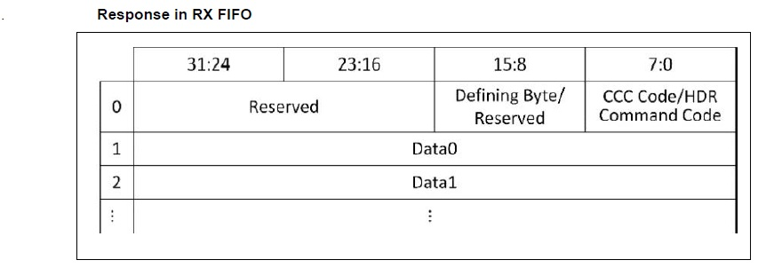
- 0x0: No Command Word. The first word from Rx FIFO is the first data word of the transfer.
- 0x1: One Command Word in the RX FIFO. Only byte 0 is valid. It contains either the HDR CMD code or the CCC Code based on the CCC bit in the response.
- 0x2: One Command Word in the RX FIFO. Only byte 0 and byte 1 are valid. It contains either the HDR CMD code or the CCC Code based on the CCC bit in the response in byte 0. It contains the defining byte for the CCC in byte 1.
- 0x4: One Command Word in the RX FIFO. All 4 bytes are valid. It contains HDR Bulk Transfer Command words 0, 1, 2 and 3.
Figure 24-39 represents how the Extended Response is distributed in the Rx-FIFO.
The Extended Response Structure is defined in Table 24-31.
The defining byte (if any) is passed to the application either through the response part from Data FIFO (for directed vendor-specific CCC) or RX-FIFO Data (for broadcast vendor-specific CCC). The defining byte (if any) for broadcast vendor-specific CCC is passed to RX-FIFO as the Target cannot differentiate between the defining byte and data payload.