
10.2.8.3 IGLOO® and ProASIC® 3 Static PLL Implementation Rules/Timing Diagrams
After you make all your selections, the configurator generates a core with your configurations. However, there are a number of restrictions in the possible values for the input and output frequencies. They are:
- Input to the clock conditioning core (CCC) must be between 1.5 and 350 MHz
- Output from the CCC must be between 1.5 and 350 MHz
- The reference input to the PLL core (fin/n) must be between 1.5 and 5.5 MHz. The PLL Core output must be between 24 and 350 (fin *m/n)
Your requested PLL values are not possible in all cases, because of the VCO input, output frequency limitations, available divider ranges and inter-dependencies between the multiple outputs. In such cases, the configurator tries to generate a value that is as close as possible to the value you requested. The actual values that the configurator can achieve are shown on the screen (in blue). If you hit generate, the core is generated with the actual values rather than the specified values. The actual values are also included in the log file for future reference.
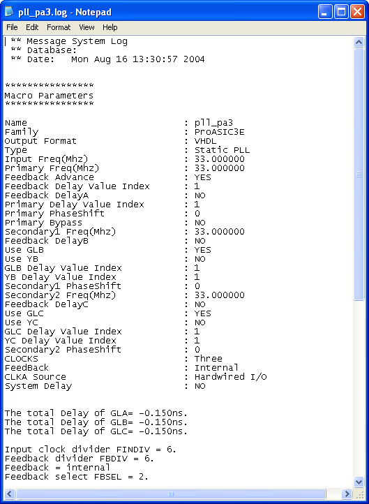
Here is a sample Log file with all the information.
If more than one output is specified, the configurator tries to find the multiplication and division factors with the smallest total error among all the outputs.