10.2.2 IGLOO® and ProASIC®3 Dynamic CCC
The only difference between the IGLOOe and ProASIC3E Dynamic CCC and IGLOO® and ProASIC® Static PLL is the availability of the dynamic shift register signals that enable a dynamic reconfiguration of the PLL.
Related Topics
Key Features
The Dynamic CCC (clock conditioning core) enables you to change the CCC configuration by shifting it in through a serial interface. You have a fixed default configuration and the two configurations can be interchanged dynamically.
The IGLOOe and ProASIC3E Clock Conditioning Circuit (CCC) contains a PLL core, delay lines, clock multipliers/dividers, PLL reset generator (you have no control over the reset), global pads and all circuitry for the selection and interconnection of the “global” pads to the global network.
The PLL Core consists of a Phase Detector, L.P. Filter and a 4-Phase VCO.
The clock conditioning circuit block is fully configurable, either through flash configuration bits (set in the programming bitstream) or through a simple asynchronous interface dynamically accessible from customer signals inside the device to permit parameter changes during device operation.
The clock conditioning circuit performs the following basic functions:
- Clock phase adjustment
- Clock delay minimization
- Clock frequency synthesis
In addition to all the functionality available in the IGLOO® and ProASIC®3 Static PLL , the Dynamic CCC prints out all the values of the configuration pins in a report. You can use these to specify the bitstream that can be shifted in through the shift register.
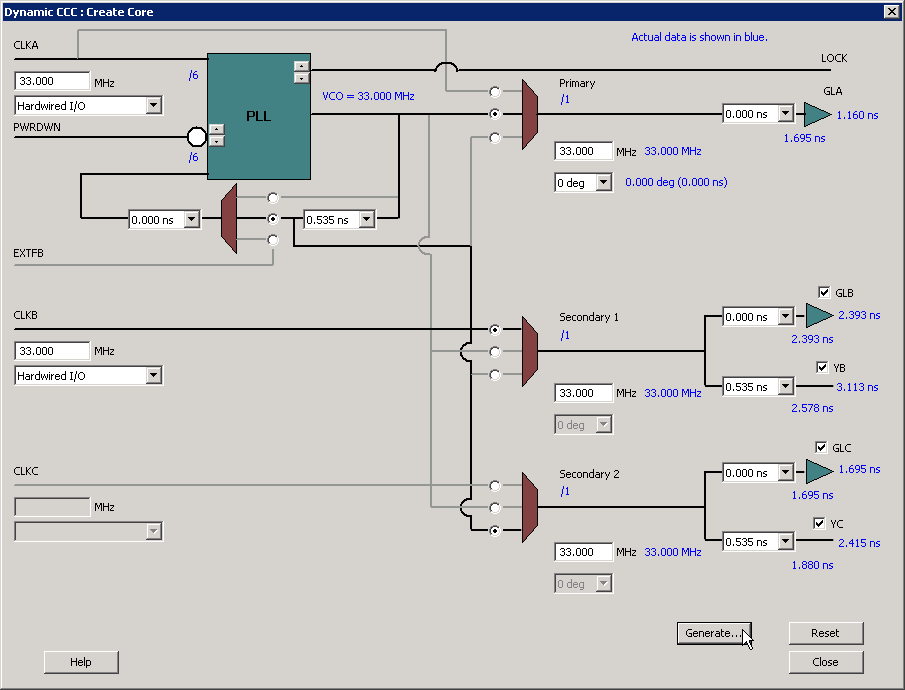
The Dynamic CCC is configured exactly the same way as the IGLOO® and ProASIC®3 Static PLL . The only differences are the Secondary 1 and Secondary 2 inputs available on the Secondary 1 and Secondary 2 outputs. The Secondary 1 and 2 inputs are available only in bypass mode.
The Dynamic CCC is shown in the following figure.