
6.14 About Physical Design Constraint (PDC) Files
A PDC file is a Tcl script file specifying physical constraints. This file can be imported and exported from Designer. Any constraint that you can enter using the PinEditor in MVN or ChipPlanner tool, you can also use in a PDC file.
Only IGLOO, Fusion, ProASIC3, and Axcelerator devices support PDC files. Designer supports the following PDC commands.
Command | Action |
|---|---|
Assigns regular nets to global clock networks by promoting the net using a CLKINT macro | |
assign_local_clock | Assigns regular nets to local clock routing (Axcelerator) or to LocalClock regions (IGLOO, Fusion, and ProASIC3) |
Assigns the macros connected to a net to a specified defined region | |
Assigns regular nets to a specific quadrant clock region (IGLOO, Fusion, and ProASIC3) | |
Assigns macros to a pre-specified region | |
Defines either a rectangular or rectilinear region | |
Removes all buffers and inverters from a given net for IGLOO, Fusion, and ProASIC3E devices | |
Restores all buffers and inverters that were removed from a given net with the delete_buffer_tree command | |
Moves only the block core (COMB, SEQ) of the specified instance (I/Os or PLLs) to the specified location on the chip | |
Moves a region to new coordinates | |
Deletes all defined regions. Placed macros are not affected. | |
Resets all attributes on a macro to the default values | |
|
Resets an I/O banks technology to the default technology | |
|
Resets net criticality to default level | |
|
set_io |
Sets the attributes of an I/O |
|
set_iobank |
Specifies the I/O bank’s technology and sets the VREF pins for the specified banks |
|
Places a given logic instance at a particular location | |
|
Overrides the compile option for either a specific block or an instance of a block | |
|
Assigns specified two-tile and four-tile macros to specified locations on the chip | |
|
Sets properties on a port in the Block flow | |
|
Preserves instances before compile so that instances are not combined | |
|
Sets net criticality, which is issued to influence placement and routing in favor of performance | |
|
Reserves the specified pins in the design | |
|
Resets the specified pins in the design that were previously reserved | |
|
Assigns clock nets to regular nets | |
|
Unassigns the specified user-defined net from a LocalClock or QuadrantClock region | |
|
Unassigns macros from a specified region, if they are assigned to that region | |
|
Unassigns macros connected to a specified net from a defined region | |
|
Unassigns the specified net from a QuadrantClock region | |
|
Removes the specified region |
PDC commands are case sensitive. However, their arguments are not.
6.14.1 PDC Syntax Conventions
The following table shows the typographical conventions that are used for the PDC command syntax.
Syntax Notation | Description |
|---|---|
command -argument | Commands and arguments appear in Courier New typeface. |
variable | Variables appear in italic Courier New typeface. You must substitute an appropriate value for the variable. |
[-argument value] [variable]+ | Optional arguments begin and end with a square bracket with one exception: if the square bracket is followed by a plus sign (+), then users must specify at least one argument. The plus sign (+) indicates that items within the square brackets can be repeated. Do not enter the plus sign character. |
PDC commands are case sensitive. However, their arguments are not.
6.14.1.1 Examples
Syntax for the assign_local_clock (Axcelerator) command followed by a sample command:
assign_local_clock -type value -net netname [LocalClock_region ]+
assign_local_clock -type hclk -net reset_n tile1a tile2a
Syntax for the set_io (Axcelerator) command followed by a sample command:
set_io portname [-iostd value][-register value][-out_drive value][-slew value][-res_pull value][-out_load value][-pinname value][-fixed value][-in_delay value]
set_io ADDOUT2 \
-iostd PCI \
-register yes \
-out_drive 16 \
-slew high \
-out_load 10 \
-pinname T21 \
-fixed yes
6.14.1.2 Wildcard Characters
You can use the following wildcard characters in names used in PDC commands:
Wildcard | What It Does |
|---|---|
\ | Interprets the next character literally |
? | Matches any single character |
* | Matches any string |
[] | Matches any single character among those listed between brackets (that is, [A-Z] matches any single character in the A-to-Z range) |
The matching function requires that you add a slash (\) before each slash in the port, instance, or net name when using wildcards in a PDC command and when using wildcards in the Find feature of the MultiView Navigator. For example, if you have an instance named “A/B12” in the netlist, and you enter that name as “A\\/B*” in a PDC command, you will not be able to find it. In this case, you must specify the name as A\\\\/B*.
6.14.1.3 Special Characters ([ ], { }, and \)
Sometimes square brackets are part of the command syntax. In these cases, you must either enclose the open and closed square brackets characters with curly brackets or precede the open and closed square brackets characters with a backslash (\). If you do not, you will get an error message.
For example:
set_iobank {mem_data_in[57]} -fixed no 7 2 or
set_iobank mem_data_in\[57\] -fixed no 7 2
6.14.1.4 Entering Arguments on Separate Lines
To enter an argument on a separate line, you must enter a backslash (\) character at the end of the preceding line of the command as shown in the following example:
set_io ADDOUT2 \
-iostd PCI \
-register Yes \
-out_drive 16 \
-slew High \
-out_load 10 \
-pinname T21 \
-fixed yes
6.14.2 PDC Naming Conventions
The names of ports, instances, and nets in an imported netlist are sometimes referred to as their original names.
6.14.2.1 Rules for Displaying Original Names
Port names appear exactly as they are defined in a netlist. For example, a port named A/B appears as A/B in ChipPlanner, PinEditor, and I/O Attribute Editor in MultiView Navigator.
Instances and nets display the original names plus an escape character (\) before each backslash (/) and each slash (\) that is not a hierarchy separator. For example, the instance named A/\B is displayed as A\/\\B.
6.14.2.2 Which Name Do I Use in PDC Commands?
The names of ports, instances, and nets in a netlist displayed in MultiView Navigator (MVN) for IGLOO, Fusion, ProASIC3 and Axcelerator devices are names taken directly from the imported netlist.
6.14.2.3 Using PDC Commands
When writing PDC commands, follow these rules:
- Always use the macro name as it appears in the netlist. (See "Merged elements" in this topic for exceptions.)
- Names from a netlist: For port names, use the names exactly as they appear in the netlist. For instance and net names, add an escape character (\) before each backslash (\) and each slash (/) that is not a hierarchy separator.
- Names from MVN and compile report: Use names as they appear in MultiView Navigator or the compile report.
- For wildcard names, always add an extra backslash (\) before each backslash.
- Always apply the PDC syntax conventions to any name in a PDC command.
The following table provides examples of names as they appear in an imported netlist and the names as they should appear in a PDC file:
Type of name and its location | Name in the imported netlist | Name to use in PDC file |
|---|---|---|
Port name in netlist | A/:B1 | A/:B1 |
Port name in MVN | A/:B1 | A/:B1 |
Instance name in a netlist | A/:B1 A$(1) | A\\/:B1 A$(1) |
Instance name in the netlist but using a wildcard character in a PDC file | A/:B1 | A\\\\/:B* |
Instance name in MVN or a compile report | A\/:B1 | A\\/:B1 |
|
Net name in a netlist |
Net1/:net1 |
Net1\\/:net1 |
|
Net name in MVN or a compile report |
Net1\/:net1 |
Net1\\/:net1 |
When exporting PDC commands, the software always exports names using the PDC rules described in this topic.
6.14.2.4 Case Sensitivity When Importing PDC Files
The following table shows the case sensitivity in the PDC file based on the source netlist.
File Type | Case Sensitivity |
|---|---|
Verilog | Names in the netlist are case sensitive. |
Edif | Names in the netlist are always case sensitive because we use the Rename clause, which is case sensitive. |
Vhdl | Names in the netlist are not case sensitive unless those names appear between slashes (\). |
For example, in VHDL, capital "A" and lowercase "a" are the same name, but \A\ and \a\ are two different names. However, in a Verilog netlist, an instance named "A10" will fail if spelled as "a10" in the set_location command:
set_location A10 (This command will succeed.) set_location a10 (This command will fail.)
6.14.2.5 Which Name to Use in the Case of Merged Elements (IGLOO, Fusion, and ProASIC3 Only)
The following table indicates which name to use in a PDC command when performing the specified operation:
Operation | Name to Use |
|---|---|
I/O connected to PLL with a hardwired connection | PLL instance name |
I/O combined with FF or DDR | I/O instance name |
Global promotion |
6.14.3 assign_global_clock
Assigns regular nets to global clock networks by promoting the net using a CLKINT macro.
assign_global_clock -net netname
6.14.3.1 Arguments
- -net netname
- Specifies the name of the net to promote to a global clock network. The net is promoted using a CLKINT macro, which you can place on a chip-wide clock location.
6.14.3.2 Supported Families
IGLOO, ProASIC3, SmartFusion, Fusion
6.14.3.3 Exceptions
The assign_global_clock command is not supported in auxiliary PDC files.
6.14.3.4 Examples
assign_global_clock -net globalReset
6.14.4 assign_local_clock (IGLOO, ProASIC3, SmartFusion and Fusion)
Assigns regular nets to LocalClock regions.
assign_local_clock -net netname-type clock_type clock_region
6.14.4.1 Arguments
- -net netname
- Specifies the name of the net to assign to a LocalClock region.
- -type clock_type
- Specifies the type of region to which the net will be assigned:
Value
Description
chip
Specifies a LocalClock region driven by a clock rib located on the middle of the chip
quadrant
Specifies one of the following:
- A QuadrantClock region
- A LocalClock region driven by a clock rib located on the top or bottom of the chip
- clock_region
-
Specifies a LocalClock region. LocalClock regions are defined as one of the following:
- A single spine defined as T# (Top spine) or B# (Bottom spine)
- A multi-spine rectangle defined as [T | B]#:[T | B]#
Spines are numbered from left to right starting at 1. The maximum spine number is a function of the die selected by the user. Please refer to the examples in this help topic.
Local clock uses clock spine resources remaining after global assignment from Input Netlist and PDC constraints. There are six chip-wide and twelve quadrant-wide clock resources per device. You may reserve portions of a clock network (chip-wide or quadrant-wide) for local clocks by assigning clock nets to regions. If there are not enough clock resources to honor all local clock assignments, the Layout command will fail.
6.14.4.2 Supported Families
IGLOO, ProASIC3, SmartFusion and Fusion
You must import the PDC file along with the netlist as a source file because Compile needs to delete buffers and legalize the netlist. Shared instances between local clocks are supported. Compile will insert buffers to legalize the netlist.
6.14.4.3 Exceptions
If the net is a clock net, it is demoted to a regular net. You will see an unassign_global_net command in the PDC file if the net is demoted to a regular net by the compiler and the assignment to local clock failed.
6.14.4.4 Examples
This example assigns the net named localReset to the chip-wide spine T1:
assign_local_clock -net localReset -type chip T1
This example assigns the net named localReset to the quadrant spines T1, T2, T3, T4, and T5, which span more than one quadrant:
assign_local_clock -net localReset -type quadrant T1:T5
This example assigns the net named localReset to the chip-wide spines T1, T2, T3, T4, T5, T6, B1, B2, B3, B4, B4, and B6:
assign_local_clock -net localReset -type chip T1:B6
6.14.5 assign_local_clock (Axcelerator)
Assigns regular nets to local clock routing.
assign_local_clock -type value -net netname[ LocalClock_region ]+
Along with the netlist, import PDC files as source files because the compiler needs to insert or delete buffers as well as legalize the netlist.
6.14.5.1 Arguments
- -type value
- Specifies the type of clock to which the net will be assigned. You can enter one of the
following values:
Value
Description
hclk
Indicates a hardwired clock.
rclk
Indicates a routed clock.
- -net netname
- Specifies the name of the net to assign to a LocalClock region. You must specify a net name that currently exists in the design.
- LocalClock_region
- You must specify at least one LocalClock region. You can define the LocalClock region at either the tile level or at the row or column level within a tile.
6.14.5.2 Supported Families
Axcelerator
6.14.5.3 Exceptions
The assign_local_clock command is not supported in auxiliary PDC files. If importing a PDC file that includes this command, you must import it as a source file.
6.14.5.4 Examples
You can cascade tiles to create one LocalClock region as follows:
assign_local_clock -type hclk -net reset_n tile1a tile2a assign_local_clock -type rclk -net reset_n tile1a tile2a
You can assign a net to one tile as follows:
assign_local_clock -type rclk -net reset_n tile1a assign_local_clock -type hclk -net reset_n tile2c
You can assign a net to a column within a tile as follows:
assign_local_clock -type hclk -net reset_n tile1a.col7 tile2a.col9
You can assign a net to a row within a tile as follows:
assign_local_clock -type rclk -net reset_n tile1a.row4 tile1a.row5
6.14.6 assign_net_macros
Assigns to a user-defined region all the macros that are connected to a net.
assign_net_macros region_name [net1]+ [-include_driver value]
6.14.6.1 Arguments
- region_name
- Specifies the name of the region to which you are assigning macros. The region must exist before you use this command. See define_region (rectangular) or define_region (rectilinear). Because the define_region command returns a region object, you can write a simple command such as assign_net_macros [define_region]+ [net]+
- net1
- You must specify at least one net name. Net names are AFL-level (Microchip flattened
netlist) names. These names match your netlist names most of the time. When they do not,
you must export AFL and use the AFL names. Net names are case insensitive. Hierarchical
net names from ADL are not allowed. You can use the following wildcard characters in net
names:
Wilcard
What It Does
\
Interprets the next character as a non-special character
?
Matches any single character
*
Matches any string
[]
Matches any single character among those listed between brackets (that is, [A-Z] matches any single character in the A-to-Z range)
- net1
- Specifies whether to add the driver of the net(s) to the region. You can enter one of
the following values:
Value
Description
Yes
Include the driver in the list of macros assigned to the region (default) .
No
Do not assign the driver to the region.
6.14.6.2 Supported Families
IGLOO, ProASIC3, SmartFusion, Fusion, Axcelerator
6.14.6.3 Exceptions
- Placed macros (not connected to the net) that are inside the area occupied by the net region are automatically unplaced.
- Net region constraints are internally converted into constraints on macros. PDC export results as a series of assign_region <region_name> macro1 statements for all the connected macros.
- If the region does not have enough space for all of the macros, or if the region constraint is impossible, the constraint is rejected and a warning message appears in the Log window.
- For overlapping regions, the intersection must be at least as big as the overlapping macro count.
- If a macro on the net cannot legally be placed in the region, it is not placed and a warning message appears in the Log window.
- Net region constraints may result in a single macro being assigned to multiple regions. These net region constraints result in constraining the macro to the intersection of all the regions affected by the constraint.
6.14.6.4 Examples
assign_net_macros cluster_region1 keyin1intZ0Z_62 -include_driver no
6.14.7 assign_quadrant_clock
Assigns regular nets to a specific quadrant clock region.
assign_quadrant_clock -net netname -quadrant quadrant_clock_region [-fixed value]
6.14.7.1 Arguments
- -net netname
- Specifies the name of the net to assign to a QuadrantClock region. You must specify a net name that currently exists in the design.
- -quadrant quadrant_clock_region
- Specifies the QuadrantClock region to which the net will be assigned. Each die has four
quadrants. QuadrantClock regions are defined as one of the following:
- UL: Upper-Left quadrant
- UR: Upper-Right quadrant
- LL: Lower-Left quadrant
- LR: Lower-Right quadrant
- -fixed value
- Specifies if the specified QuadrantClock region is locked. If you do not want the Global
Assigner to remove it, then lock the region. You can enter one of the following
values:
Value
Description
yes
The QuadrantClock region is locked.
no
The QuadrantClock region is not locked.
6.14.7.2 Supported Families
IGLOO, ProASIC3, SmartFusion and Fusion
6.14.7.3 Exceptions
This command is not supported in auxiliary PDC files. If importing a PDC file that includes this command, you must import it as a source file.
6.14.7.4 Examples
This example assigns the net named FRAMEN_in to the quadrant clock in the upper-left (UL) quadrant of the chip:
assign_quadrant_clock -net FRAMEN_in -quadrant UL
This example assigns the net named STOPN_in to the quadrant clock in the lower-right (LR) quadrant of the chip:
assign_quadrant_clock -net STOPN_in -quadrant LR
This example assigns the net named n32 to the quadrant clock in the lower-right (LR) quadrant of the chip and locks it so that the Global Assigner cannot delete the quadrant region:
assign_quadrant_clock -net n32 -quadrant LR -fixed yes
6.14.8 assign_region
Constrains a set of macros to a specified region.
assign_region region_name [ macro_name]+
6.14.8.1 Arguments
- region_name
- Specifies the region to which the macros are assigned. The macros are constrained to this region. Because the define_region command returns a region object, you can write a simpler command such as assign_region [define_region]+ [macro_name]+
- macro_name
- Specifies the macro(s) to assign to the region. You must specify at least one macro
name. You can use the following wildcard characters in macro names:
Wildcard
What It Does
\
Interprets the next character as a non-special character
?
Matches any single character
*
Matches any string
[]
Matches any single character among those listed between brackets (that is, [A-Z] matches any single character in the A-to-Z range)
6.14.8.2 Supported Families
IGLOO, ProASIC3, SmartFusion, Fusion and Axcelerator
6.14.8.3 Exceptions
- The region must be created before you can assign macros to it.
- You can assign only hard macros or their instances to a region. You cannot assign a group name. A hard macro is a logic cell consisting of one or more silicon modules with locked relative placement.
- You can assign a collection of macros by providing a prefix to their names.
6.14.8.4 Examples
In the following example, two macros are assigned to a region:
assign_region cluster_region1 des01/G_2722_0_and2 des01/data1_53/U0
In the following example, all macros whose names have the prefix des01/Counter_1 (or all macros whose names match the expression des01/Counter_1/*) are assigned to a region:
assign_region User_region2 des01/Counter_1
6.14.9 define_region
Defines either a rectangular region or a rectilinear region.
define_region [-name region_name ] -type region_type [x1 y1 x2 y2]+ [-color value] [-route value] [-push_place value]
6.14.9.1 Arguments
- -name region_name
- Specifies the region name. The name must be unique. Do not use reserved names such as “bank0” and “bank<N>” for region names. If the region cannot be created, the name is empty. A default name is generated if a name is not specified in this argument.
- -type region_type
- Specifies the region type. The default is inclusive. The following table shows the
acceptable values for this argument:
Region Type Value
Description
Empty
Empty regions cannot contain macros.
Exclusive
Only contains macros assigned to the region.
Inclusive
Can contain macros both assigned and unassigned to the region.
- x1 y1 x2 y2
- Specifies the series of coordinate pairs that constitute the region. These rectangles may or may not overlap. They are given as x1 y1 x2 y2 (where x1, y1 is the lower left and x2 y2 is the upper right corner in row/column coordinates). You must specify at least one set of coordinates.
- -color value
- Specifies the color of the region. The following list shows the recommended values for
this argument:
- 16776960
- 65280
- 16711680
- 16760960
- 255
- 16711935
- 65535
- 33023
- 8421631
- 9568200
- 8323199
- 12632256
- -route value
- Specifies whether to direct the routing of all nets internal to a region to be
constrained within that region. A net is internal to a region if its source and
destination pins are assigned to the region. This option only applies to IGLOO, Fusion,
and ProASIC3 families. You can enter one of the following values:
Constrain Routing Value
Description
Yes
Constrain the routing of nets within the region as well as the placement.
No
Do not constrain the routing of nets within the region. Only constrain the placement. This is the default value.
- -push_place value
- Specifies whether to over-constrain placement for routability, contracting or expanding
the size of a placement region, depending on the region's type. To use this option, you
must also specify the route option (-route yes). This option only applies to IGLOO,
Fusion, and ProASIC3 families. You can enter one of the following values:
Over-constrain Placement Value
Description
Yes
Adjust the size of a placement region according to its type.
No
Do not adjust the size of a placement region. This is the default value.
6.14.9.2 Supported Families
IGLOO, ProASIC3, SmartFusion, Fusion, Axcelerator and RTAX-S
6.14.9.3 Description
Unlocked macros in empty or exclusive regions are unassigned from that region. You cannot create empty regions in areas that contain locked macros.
You can define a rectilinear region only in a PDC file; you cannot define a rectilinear region using the MultiView Navigator tool.
Use inclusive or exclusive region constraints if you intend to assign logic to a region. An inclusive region constraint with no macros assigned to it has no effect. An exclusive region constraint with no macros assigned to it is equivalent to an empty region.
6.14.9.4 Exceptions
If macros assigned to a region exceed the area's capacity, an error message appears in the Log window.
6.14.9.5 Examples
The following example defines an empty rectangular region.
define_region -name cluster_region1 -type empty 100 46 102 46
The following example defines a rectilinear region with the name RecRegion. This region contains two rectangular areas.
define_region -name RecRegion -type Exclusive 0 40 3 42 0 77 7 79
The following examples define three regions with three different colors:
define_region -name UserRegion0 -color 128 50 19 60 25
define_region -name UserRegion1 -color 16711935 11 2 55 29
define_region -name UserRegion2 -color 8388736 61 6 69 19
6.14.10 delete_buffer_tree
delete_buffer_tree [netname]+
Instructs the Compile command to remove all buffers and inverters from a given net. In the IGLOO and ProASIC3 architectures, inverters are considered buffers because all tile inputs can be inverted. This rule is also true for all Flash architectures but not for Antifuse architectures.
6.14.10.1 Arguments
- netname
- Specifies the names of the nets from which to remove buffer or inverter trees. This
command takes a list of names. You must specify at least one net name. You can use the
following wildcard characters in net names:
Wildcard
What It Does
\
Interprets the next character as a non-special character
?
Matches any single character
*
Matches any string
[]
Matches any single character among those listed between brackets (that is, [A-Z] matches any single character in the A-to-Z range)
6.14.10.2 Supported Families
IGLOO, ProASIC3, SmartFusion and Fusion
6.14.10.3 Exceptions
The delete_buffer_tree command is not supported in auxiliary PDC files.
6.14.10.4 Examples
delete_buffer_tree net1 delete_buffer_tree netData\[*\]
6.14.11 dont_touch_buffer_tree
Undoes the delete_buffer_tree command. That is, it restores all buffers and inverters that were removed from a given net.
This command is not supported in auxiliary PDC files.
dont_touch_buffer_tree [netname]+
6.14.11.1 Arguments
- netname
- Specifies the names of the nets from which to restore buffers or inverters. This command
takes a list of names. You must specify at least one net name. Separate each net name with
a space. You can use the following wildcard characters in net names:
Wildcard
What It Does
\
Interprets the next character as a non-special character
?
Matches any single character
*
Matches any string
[]
Matches any single character among those listed between brackets (that is, [A-Z] matches any single character in the A-to-Z range)
6.14.11.2 Supported Families
IGLOO, ProASIC3, SmartFusion and Fusion
6.14.11.3 Exceptions
None
6.14.11.4 Example
dont_touch_buffer_tree net1 net2 dont_touch_buffer_tree netData\[*\]
6.14.12 move_block
Moves a Designer block from its original, locked placement by preserving the relative placement between the instances. You can move the Designer block to the left, right, up, or down.
Note: If possible, routing is preserved when you move the blocks for IGLOO, Fusion and ProASCI3 families.
move_block -inst_name instance_name -up y -down y -left x -right x -non_logic value
6.14.12.1 Arguments
- -inst_name instance_name
- Specifies the name of the instance to move. If you do not know the name of the instance, run a compile report or look at the names shown in the Block tab of the MultiView Navigator Hierarchy view.
- -up y
- Moves the block up the specified number of rows. The value must be a positive integer.
- -down y
- Moves the block down the specified number of rows. The value must be a positive integer.
- -left x
- Moves the block left the specified number of columns. The value must be a positive integer.
- -right x
- Moves the block right the specified number of columns. The value must be a positive integer.
- -non_logic value
- Specifies what to do with the non-logic part of the block, if one exists. The following
table shows the acceptable values for this argument:
Value
Description
move
Move the entire block.
keep
Move only the logic portion of the block (COMB/SEQ) and keep the rest locked in the same previous location, if there is no conflict with other blocks.
unplace
Move only the logic portion of the block (COMB/SEQ) and unplace the rest of it, such as I/Os and RAM.
6.14.12.2 Supported Families
IGLOO, ProASIC3, SmartFusion, Fusion and Axcelerator
6.14.12.3 Description
This command moves a Designer block from its original, locked position to a new position.
You can move the entire block or just the logic part of it. You must use the -non_logic argument to specify what to do with the non-logic part of the block. You can find placement information about the block in the Block report. From the Tools menu in the designer software, choose Reports > Block > Interface to display the report that shows the location of the blocks.
The -up, -down, -left, and -right arguments enable you to specify how to move the block from its original placement. You cannot rotate the block, but the relative placement of macros within the block will be preserved and the placement will be locked. However, routing will be lost. You can either use the ChipPlanner tool or run a Block report to determine the location of the block.
The -non_logic argument enables you to move a block that includes non-logic instances, such as RAM or I/Os that are difficult to move. Once you have moved a part of a block, you can unplace the remaining parts of the block and then place them manually as necessary.
If designing for the Axcelerator family, we recommend that you move the block to the left or right by increments of 10 to match the clusters, or if your design includes RAM, we recommend that you move the block up or down by increments of 7 to match the RAM clusters. For IGLOO, Fusion, and ProASIC3 families, we recommend that you move the block left or right by increments of 16 to match the RAM clusters and the spine columns. If your block is driven by a quadrant clock, be sure not to move the macros driven by this clock outside of the quadrant.
6.14.12.4 Exceptions
- You must import this PDC command as a source file, not as an auxiliary file.
- You must use this PDC command if you want to preserve the relative placement and routing (if possible) of a block you are instantiating many times in your design. Only one instance will be preserved by default. To preserve other instances, you must move them using this command.
6.14.12.5 Examples
The following example moves the entire block (instance name instA) 16 columns to the right and 16 rows up:
move_block -inst_name instA -right 16 -up 16 -non_logic move
The following example moves only the logic portion of the block and unplaces the rest by 16 columns to the right and 16 rows up.
move_block -inst_name instA –right 16 –up 16 –non_logic unplace
6.14.13 move_region
Moves the named region to the coordinates specified.
move_region region_name [x1 y1 x2 y2]+
6.14.13.1 Arguments
- region_name
- Specifies the name of the region to move. This name must be unique.
- x1 y1 x2 y2
- Specifies the series of coordinate pairs representing the location in which to move the named region. These rectangles can overlap. They are given as x1 y1 x2 y2, where x1, y1 represents the lower-left corner of the rectangle and x2 y2 represents the upper-right corner. You must specify at least one set of coordinates.
6.14.13.2 Supported Families
IGLOO, ProASIC3, SmartFusion, Fusion and Axcelerator
6.14.13.3 Exceptions
None
6.14.13.4 Examples
This example moves the region named RecRegion to a new region which is made up of two rectangular areas:
move_region RecRegion 0 40 3 42 0 77 7 79
6.14.14 reserve
Reserves the named pins in the current device package.
reserve -pinname "list of package pins"
6.14.14.1 Arguments
- -pinname "list of package pins"
- Specifies the package pin name(s) to reserve. You can reserve one or more pins.
6.14.14.2 Supported Families
IGLOO, ProASIC3, SmartFusion, Fusion and Axcelerator
6.14.14.3 Exceptions
None.
6.14.14.4 Examples
reserve -pinname "F2" reserve -pinname "F2 B4 B3" reserve -pinname "124 17"
6.14.15 reset_floorplan
Deletes all regions.
reset_floorplan
6.14.15.1 Arguments
None
6.14.15.2 Supported Families
IGLOO, ProASIC3, SmartFusion, Fusion and Axcelerator
6.14.15.3 Exceptions
None
6.14.15.4 Examples
reset_floorplan
6.14.16 reset_io
Restores all attributes of an I/O macro to its default values. Also, if the port is assigned, it will become unassigned.
reset_io portname -attributes value
6.14.16.1 Arguments
- portname
- Specifies the port name of the I/O macro to be reset. You can use the following wildcard
characters in port names:
Wildcard
Waht It Does
\
Interprets the next character as a non-special character
?
Matches any single character
*
Matches any string
[]
Matches any single character among those listed between brackets (that is, [A-Z] matches any single character in the A-to-Z range)
- -attributes value
- Preserve or not preserve the I/O attributes during incremental flow. The following table
shows the acceptable values for this argument:
Value
Description
yes
Unassigns all of the I/O attributes and resets them to their default values.
no
Unassigns only the port.
6.14.16.2 Supported Families
IGLOO, ProASIC3, SmartFusion, Fusion and Axcelerator
6.14.16.3 Exceptions
None
6.14.16.4 Examples
reset_io a
Resets the I/O macro “a” to the default I/O attributes and unassigns it.
reset_io b_*
Resets all I/O macros beginning with "b_" to the default I/O attributes and unassigns them.
reset_io b -attributes no
Only unassigns port b from its location.
6.14.17 reset_iobank
reset_iobank bankname
Resets an I/O bank’s technology to the default technology, which is specified using the Designer software in the Device Selection Wizard.
6.14.17.1 Arguments
- bankname
- Specifies the I/O bank to be reset to the default technology. For example, for ProASIC3E and Axcelerator devices, I/O banks are numbered 0-7 (bank0, bank1,.. bank7).
6.14.17.2 Supported Families
IGLOO, ProASIC3, SmartFusion, Fusion and Axcelerator
6.14.17.3 Exceptions
Any pins that are assigned to the specified I/O bank but are incompatible with the default technology are unassigned.
6.14.17.4 Examples
The following example resets I/O bank 4 to the default technology:
reset_iobank bank4
6.14.18 reset_net_critical
Resets the critical value to its default. Net criticality can vary from 1 to 10, with 1 being the least critical and 10 being the most. The default is 5. Criticality numbers are used in timing driven place-and-route.
reset_net_critical [netname]+
Increasing a net’s criticality forces place-and-route to keep instances connected to the net as close as possible, at the cost of other (less critical) nets.
6.14.18.1 Arguments
- netname
- Specifies the name of the net to be reset to the default critical value. You must
specify at least one net name. You can use the following wildcard characters in net
names:
Wildcard
What It Does
\
Interprets the next character as a non-special character
?
Matches any single character
*
Matches any string
[]
Matches any single character among those listed between brackets (that is, [A-Z] matches any single character in the A-to-Z range)
6.14.18.2 Supported Families
Axcelerator
6.14.18.3 Exceptions
None
6.14.18.4 Examples
This example resets the net preset_a:
reset_net_critical preset_A
6.14.19 set_block_options
Overrides the compile option for placement or routing conflicts for an instance of a Designer block.
set_block_options -inst_name instance_name -placement_conflicts value -routing_conflicts
value
6.14.19.1 Arguments
- -inst_name instance_name
- Specifies the name of the instance of the block. If you do not know the name of the instance, run a compile report or look at the names shown in the Block tab of the MultiView Navigator Hierarchy view.
- -placement_conflicts value
- Specifies what to do when the designer software encounters a placement conflict. The
following table shows the acceptable values for this argument:
Value
Description
error
Compile errors out if any instance from a Designer block becomes unplaced or its routing is deleted. This is the default compile option.
resolve
If some instances get unplaced for any reason, the non-conflicting elements remaining are also unplaced. Basically, if there are any conflicts, nothing from the block is kept.
keep
If some instances get unplaced for any reason, the non-conflicting elements remaining are preserved but not locked. Therefore, the placer can move them into another location if necessary.
lock
If some instances get unplaced for any reason, the non-conflicting elements remaining are preserved and locked.
discard
Discards any placement from the block, even if there are no conflicts.
- -routing_conflicts value
- Specifies what to do when the designer software encounters a routing conflict. The
following table shows the acceptable values for this argument:
Value
Description
error
Compile errors out if any route in any preserved net from a Designer block is deleted.
resolve
If a route is removed from a net for any reason, the routing for the non-conflicting nets is also deleted. Basically, if there are any conflicts, no routes from the block are kept.
keep
If a route is removed from a net for any reason, the routing for the non-conflicting nets is kept unlocked. Therefore, the router can re-route these nets.
lock
If routing is removed from a net for any reason, the routing for the non-conflicting nets is kept as locked, and the router will not change them. This is the default compile option.
discard
Discards any routing from the block, even if there are no conflicts.
6.14.19.2 Supported Families
IGLOO, ProASIC3, SmartFusion, Fusion and Axcelerator
6.14.19.3 Description
This command enables you to override the compile option for placement or routing conflicts for an instance of a block.
6.14.19.4 Exceptions
- You must import this PDC command as a source file, not as an auxiliary file.
- If placement is discarded, the routing is automatically discarded too.
6.14.19.5 Examples
This example makes the designer software display an error if any instance from a block becomes unplaced or the routing is deleted:
set_block_options -inst_name instA -placement_conflicts ERROR -routing_conflicts ERROR
6.14.20 set_io (IGLOOe, Fusion, ProASIC3L, and ProASIC3E)
set_io portname [-pinname value][-fixed value][-iostd value][-out_drive value][-slew value][-res_pull value][-schmitt_trigger value] [-in_delay value] [-skew value][-out_load value][-register value]
Sets the attributes of an I/O for IGLOOe, Fusion, ProASIC3L, and ProASIC3E devices. You can use the set_io command to assign an I/O technology, the I/O attributes, place, or lock the I/O at a given pin location.
6.14.20.1 Arguments
- portname
- Specifies the portname of the I/O macro to set.
- -pinname value
- Assigns the I/O macro to the specified pin.
- -fixed value
- Locks or unlocks the location of this I/O. Locked pins are not moved during layout.
Therefore, locking this I/O ensures that the specified pin location is used during
place-and-route. If this I/O is not currently assigned, then this argument has no effect.
The following table shows the acceptable values for the -fixed attribute:
Value
Description
yes
The location of this I/O is locked
no
The location of this I/O is unlocked
- -iostd value
- Sets the I/O standard for this macro. Choosing a standard allows the software to set
other attributes such as the slew rate and output loading. If the voltage standard used
with the I/O is not compatible with other I/Os in the I/O bank, then assigning an I/O
standard to a port will invalidate its location and automatically unassign the I/O. The
following table shows the acceptable values for the -iostd attribute for IGLOOe, Fusion,
ProASIC3L, and ProASIC3E devices:
Value
Description
LVTTL
(Low-Voltage TTL) A general purpose standard (EIA/JESDSA) for 3.3 V applications. It uses an LVTTL input buffer and a push-pull output buffer.
LVCMOS33
(Low-Voltage CMOS for 3.3 Volts) An extension of the LVCMOS standard (JESD 8-5) used for general-purpose 3.3 V applications.
LVCMOS25
(Low-Voltage CMOS for 2.5 Volts) An extension of the LVCMOS standard (JESD 8-5) used for general-purpose 2.5 V applications.
LVCMOS25_50
(Low-Voltage CMOS for 2.5 and 5.0 Volts) An extension of the LVCMOS standard (JESD 8-5) used for general-purpose 2.5 V and 5.0V applications.
LVCMOS18
(Low-Voltage CMOS for 1.8 Volts) An extension of the LVCMOS standard (JESD 8-5) used for general-purpose 1.8 V applications. It uses a
3.3 V-tolerant CMOS input buffer and a push-pull output buffer.
LVCMOS15
(Low-Voltage CMOS for 1.5 volts) An extension of the LVCMOS standard (JESD 8-5) used for general-purpose 1.5 V applications. It uses a 3.3 V-tolerant CMOS input buffer and a push-pull output buffer.
LVCMOS12
(Low-Voltage CMOS for 1.2 volts) An extension of the LVCMOS standard (JESD 8-5) used for general-purpose 1.2 V applications. This I/O standard is supported only in ProASIC3L and the IGLOO family of devices.
LVDS
A moderate-speed differential signaling system, in which the transmitter generates two different voltages which are compared at the receiver. It requires that one data bit be carried through two signal lines; therefore, you need two pins per input or output. It also requires an external resistor termination. The voltage swing between these two signal lines is approximately 350mV (millivolts).
LVPECL
PECL is another differential I/O standard. It requires that one data bit is carried through two signal lines; therefore, two pins are needed per input or output. It also requires an external resistor termination. The voltage swing between these two signal lines is approximately 850mV. When the power supply is +3.3 V, it is commonly referred to as low-voltage PECL (LVPECL).
PCI
(Peripheral Component Interface) Specifies support for both 33 MHz and 66 MHz PCI bus applications. It uses an LVTTL input buffer and a push-pull output buffer. With the aid of an external resistor, this I/O standard can be 5V-compliant for most families, excluding ProASIC3 families.
PCIX
(Peripheral Component Interface Extended) An enhanced version of the PCI specification that can support higher average bandwidth; it increases the speed that data can move within a computer from 66 MHz to 133 MHz.
PCI-X is backward-compatible, which means that devices can operate at conventional PCI frequencies (33 MHz and 66 MHz). PCI-X is also more fault tolerant than PCI.
HSTLI
(High-Speed Transceiver Logic) A general-purpose, high-speed 1.5 V bus standard (EIA/JESD 8-6). It has four classes, of which Microchip supports Class I and II for IGLOOe and ProASIC3E devices. It requires a differential amplifier input buffer and a push-pull output buffer.
HSTLII
(High-Speed Transceiver Logic) A general-purpose, high-speed 1.5 V bus standard (EIA/JESD 8-6). It has four classes, of which Microchip supports Class I and II for IGLOOe and ProASIC3E devices. It requires a differential amplifier input buffer and a push-pull output buffer.
SSTL3I
(Stub Series Terminated Logic for 3.3 V) A general-purpose 3.3 V memory bus standard (JESD8-8). It has two classes, of which Microchip supports both. It requires a differential amplifier input buffer and a push-pull output buffer.
SSTL3II
See SSTL3I above.
SSTL2I
(Stub Series Terminated Logic for 2.5 V) A general-purpose 2.5 V memory bus standard (JESD8-9). It has two classes, of which Microchip supports both. It requires a differential amplifier input buffer and a push-pull output buffer.
SSTL2II
See SSTL2I above.
GTL25
A low-power standard (JESD 8.3) for electrical signals used in CMOS circuits that allows for low electromagnetic interference at high speeds of transfer. It has a voltage swing between 0.4 volts and 1.2 volts, and typically operates at speeds of between 20 and 40MHz. The VCCI must be connected to 2.5 volts.
GTL33
Same as GTL 2.5 V, except the VCCI must be connected to 3.3 volts.
GTLP25
(Gunning Transceiver Logic Plus) A high-speed bus standard (JESD8.3). It requires a differential amplifier input buffer and an open-drain output buffer. Even though output is open-drain, IGLOO (excluding the IGLOO device), ProASIC3, Axcelerator families, support still needs the VCCI to be connected to 2.5 V or 3.3 V.
GTLP33
See GTLP33 above.
- -out_drive value
- Sets the strength of the output buffer to 2, 4, 6, 8, 12, 16, or 24 in mA, weakest to
strongest. The list of I/O standards for which you can change the output drive and the
list of values you can assign for each I/O standard is family-specific. Not all I/O
standards have a selectable output drive strength. Also, each I/O standard has a different
range of legal output drive strength values. The values you can choose from depend on
which I/O standard you have specified for this command. See the "Slew and Out_drive
Settings" table under "Exceptions" in this topic for possible values. Also, refer to the
ProASIC3E and IGLOOe datasheets for more information. The following table shows the
acceptable values for the -out_drive attribute:
Value
Description
2
Sets the output drive strength to 2mA
4
Sets the output drive strength to 4mA
6
Sets the output drive strength to 6mA
8
Sets the output drive strength to 8mA
12
Sets the output drive strength to 12mA
16
Sets the output drive strength to 16mA
24
Sets the output drive strength to 24mA
- -slew value
- Sets the output slew rate. Slew control affects only the falling edges for some families. For ProASIC3, IGLOO, Fusion, and Axcelerator families, slew control affects both rising and falling edges. Whether you can use the slew attribute depends on which I/O standard you have specified for this command.
- -res_pull value
- Allows you to include a weak resistor for either pull-up or pull-down of the input
buffer. Not all I/O standards have a selectable resistor pull option. The following table
shows the acceptable values for the -res_pull attribute:
Value
Description
up
Includes a weak resistor for pull-up of the input buffer
down
Includes a weak resistor for pull-down of the input buffer
none
Does not include a weak resistor
- -schmitt_trigger value
- Specifies whether this I/O has an input schmitt trigger. The schmitt trigger introduces
hysteresis on the I/O input. This allows very slow moving or noisy input signals to be
used with the part without false or multiple I/O transitions taking place in the I/O. The
following table shows the acceptable values for the -schmitt_trigger attribute:
Value
Description
on
Turns the schmitt trigger on
off
Turns the schmitt trigger off
- -in_delay value
- Specifies whether this I/O has an input delay. You can specify an input delay between 0
and 7. The input delay is not a delay value but rather a selection from 0 to 7. The actual
value is a function of the operating conditions and is automatically computed by the delay
extractor when a timing report is generated. The following table shows the acceptable
values for the -in_delay attribute:
Value
Description
off
This I/O does not have an input delay
0
Sets the input delay to 0
1
Sets the input delay to 1
2
Sets the input delay to 2
3
Sets the input delay to 3
4
Sets the input delay to 4
5
Sets the input delay to 5
6
Sets the input delay to 6
7
Sets the input delay to 7
- -skew value
- Specifies whether there is a fixed additional delay between the enable/disable time for
a tristatable I/O. (A tristatable I/O is an I/O with three output states: high, low, and
high impedance.) The following table shows the acceptable values for the -skew
attribute:
Value
Description
on
Yes, there is a fixed additional delay
off
No, there is not a fixed additional delay
- -out_load value
- Determines what Timer will use as the loading on the output pin. This attribute applies only to outputs. You can enter a capacitive load as an integral number of picofarads (pF). Specify an integer between 0 and 1023 pF.
- -register value
- Specifies whether the register will be combined into the I/O. If this option is yes, the
combiner combines the register into the I/O module if possible. This option overrides the
default setting in the Compile options. I/O registers are off by default. The following
table shows the acceptable values for the -register attribute:
Value
Description
yes
Register combining is allowed on this I/O
no
Register combining is not allowed on this I/O
6.14.20.2 Supported Families
IGLOOe, ProASIC3L, ProASIC3E, SmartFusion and Fusion devices
6.14.20.3 Exceptions
- If an argument is not specified, the value is not changed, as long as it is consistent with other settings. If setting an attribute invalidates the I/Os location, then the I/O is unassigned.
- You can specify an out_drive strength and slew
rate only for certain I/O standards per family. Not all I/O standards have a selectable
output drive strength or slew. The following table shows I/O standards for which you can
specify a slew and out_drive setting:
I/O Standard
Output
Slew
2
4
6
8
12
16
24
LVTTL
X
X
X
X
X
X
X
High Low
LVCMOS33
X
X
X
X
X
X
X
High Low
LVCMOS25
X
X
X
X
X
X
X
High Low
LVCMOS25_50
X
X
X
X
X
X
X
High Low
LVCMOS18
x
x
x
x
-
-
-
High Low
LVCMOS15
x
x
-
-
-
-
-
High Low
LVCMOS12
x
-
-
-
-
-
-
High Low
PCIX
-
-
-
-
-
-
-
High Low
AGL030 and AGL015 do not support 2mA. They only support 1mA.
6.14.20.4 Examples
set_io IO_in\[2\] -iostd LVPECL \
-slew low \
-skew off \
-schmitt_trigger off \
-in_delay 0 \
-register no \
-pinname 366 \
-fixed no
6.14.21 set_io (IGLOO PLUS)
Sets the attributes of an I/O for IGLOO PLUS devices. You can use the set_io command to assign an I/O technology, the I/O attributes, place, or lock the I/O at a given pin location.
set_io portname [-pinname value][-fixed value][-iostd value][-out_drive value][-slew value][-res_pull value][-schmitt_trigger value] -out_load value][-register value] [-hold_state value]
Document the exported set_io option ‘-DIRECTION’ in the the OLH? (mark these topics with red asterisk in the toc)
6.14.21.1 Arguments
- portname
- Specifies the portname of the I/O macro to set.
- -pinname value
- Assigns the I/O macro to the specified pin.
- -fixed value
- Locks or unlocks the location of this I/O. Locked pins are not moved during layout.
Therefore, locking this I/O ensures that the specified pin location is used during
place-and-route. If this I/O is not currently assigned, then this argument has no effect.
The following table shows the acceptable values for the -fixed attribute:
Value
Description
yes
The location of this I/O is locked
no
The location of this I/O is unlocked
- -iostd value
- Sets the I/O standard for this macro. Choosing a standard allows the software to set
other attributes such as the slew rate and output loading. If the voltage standard used
with the I/O is not compatible with other I/Os in the I/O bank, then assigning an I/O
standard to a port will invalidate its location and automatically unassign the I/O. The
following table shows the acceptable values for the -iostd attribute for IGLOO PLUS
devices:
Value
Description
LVTTL
(Low-Voltage TTL) A general purpose standard (EIA/JESDSA) for 3.3 V applications. It uses an LVTTL input buffer and a push-pull output buffer.
LVCMOS33
(Low-Voltage CMOS for 3.3 Volts) An extension of the LVCMOS standard (JESD 8-5) used for general-purpose 3.3 V applications.
LVCMOS25
(Low-Voltage CMOS for 2.5 Volts) An extension of the LVCMOS standard (JESD 8-5) used for general-purpose 2.5 V applications.
LVCMOS18
(Low-Voltage CMOS for 1.8 Volts) An extension of the LVCMOS standard (JESD 8-5) used for general-purpose 1.8 V applications. It uses a 3.3 V-tolerant CMOS input buffer and a push-pull output buffer.
LVCMOS15
(Low-Voltage CMOS for 1.5 volts) An extension of the LVCMOS standard (JESD 8-5) used for general-purpose 1.5 V applications. It uses a 3.3 V-tolerant CMOS input buffer and a push-pull output buffer.
LVCMOS12
(Low-Voltage CMOS for 1.2 volts) An extension of the LVCMOS standard (JESD 8-5) used for general-purpose 1.2 V applications. This I/O standard is supported only in ProASIC3L and the IGLOO family of devices.
- -out_drive value
- Sets the strength of the output buffer to 2, 4, 6, 8, 12, or 16 in mA, weakest to
strongest. The list of I/O standards for which you can change the output drive and the
list of values you can assign for each I/O standard is family-specific. Not all I/O
standards have a selectable output drive strength. Also, each I/O standard has a different
range of legal output drive strength values. The values you can choose from depend on
which I/O standard you have specified for this command. See the "Slew and Out_drive
Settings" table under "Exceptions" in this topic for possible values. Also, refer to the
IGLOO PLUS datasheet for more information. The following table shows the acceptable values
for the -out_drive attribute:
Value
DescriptiT
2
Sets the output drive strength to 2mA
4
Sets the output drive strength to 4mA
6
Sets the output drive strength to 6mA
8
Sets the output drive strength to 8mA
12
Sets the output drive strength to 12mA
16
Sets the output drive strength to 16mA
- -slew value
- Sets the output slew rate. Slew control affects only the falling edges for some families. For ProASIC3, IGLOO, Fusion, and Axcelerator families, slew control affects both rising and falling edges. Not all I/O standards have a selectable slew. Whether you can use the slew attribute depends on which I/O standard you have specified for this command.
- -res_pull value
- Allows you to include a weak resistor for either pull-up or pull-down of the input
buffer. Not all I/O standards have a selectable resistor pull option. The following table
shows the acceptable values for the -res_pull attribute:
Value
Description
up
Includes a weak resistor for pull-up of the input buffer
down
Includes a weak resistor for pull-down of the input buffer
none
Does not include a weak resistor
- -schmitt_trigger value
- Specifies whether this I/O has an input schmitt trigger. The schmitt trigger introduces
hysteresis on the I/O input. This allows very slow moving or noisy input signals to be
used with the part without false or multiple I/O transitions taking place in the I/O. The
following table shows the acceptable values for the -schmitt_trigger attribute:
Value
Description
on
Turns the schmitt trigger on
off
Turns the schmitt trigger off
- -out_load value
- Determines what Timer will use as the loading on the output pin. This attribute applies only to outputs. You can enter a capacitive load as an integral number of picofarads (pF). Specify an integer between 0 and 1023pF. The default is 5pF for all IGLOO devices.
- -register value
- pecifies whether the register will be combined into the I/O. If this option is yes, the
combiner combines the register into the I/O module if possible. This option overrides the
default setting in the Compile options. I/O registers are off by default. The following
table shows the acceptable values for the -register attribute:See I/O Register Combining Rules for more details.
Value
Description
yes
Register combining is allowed on this I/O
no
Register combining is not allowed on this I/O
- -hold_state value
- Preserves the previous state of the I/O. By default, all the I/Os become tristated when
the device goes into Flash*Freeze mode. (A tristatable I/O is an I/O with three output
states: high, low, and high impedance.) You can override this default using the hold_state
attribute. When you set the hold_state to True, the I/O remains in the same state in which
it was functioning before the device went into Flash*Freeze mode. The following table
shows the acceptable values for the -skew attribute:
Value
Description
on
Preserves the previous state of the I/O
off
Does not preserve the previous state of the I/O
6.14.21.2 Supported Families
IGLOO PLUS
6.14.21.3 Exceptions
- If an argument is not specified, the value is not changed, as long as it is consistent with other settings. If setting an attribute invalidates the I/Os location, then the I/O is unassigned.
- You can specify an out_drive strength and slew
rate only for certain I/O standards per family. Not all I/O standards have a selectable
output drive strength or slew. The following table shows I/O standards for which you can
specify a slew and out_drive setting:
I/O Standard
Output
Slew
2
4
6
8
12
16
LVTTL
X
X
X
X
X
X
High Low
LVCMOS33
X
X
X
X
X
X
High Low
LVCMOS25
X
X
X
X
X
X
High Low
LVCMOS18
X
X
X
X
-
-
High Low
LVCMOS15
X
X
-
-
-
-
High Low
LVCMOS12
x
-
-
-
-
-
High Low
PCI
-
-
-
-
-
-
High Low
PCIX
-
-
-
-
-
-
High Low
6.14.21.4 Examples
set_io IO_in\[2\] -iostd LVPECL \
-slew low \
-schmitt_trigger off \
-register no \
-pinname 366 \
-fixed no
6.14.22 set_io (IGLOO and ProASIC3)
Sets the attributes of an I/O for IGLOO and ProASIC3 devices. You can use the set_io command to assign an I/O technology, the I/O attributes, assign, or lock the I/O at a given pin location.
set_io portname [-pinname value][-fixed value][-iostd value][-out_drive value][-slew value][-res_pull value][-out_load value][-skew value][-register value]
6.14.22.1 Arguments
- portname
- Specifies the portname of the I/O macro to set.
- -pinname value
- Assigns the I/O macro to the specified pin.
- -fixed value
- Locks or unlocks the location of this I/O. Locked pins are not moved during layout.
Therefore, locking this I/O ensures that the specified pin location is used during
place-and-route. If this I/O is not currently assigned, then this argument has no effect.
The following table shows the acceptable values for the -fixed attribute:
Value
Description
yes
The location of this I/O is locked
no
The location of this I/O is unlocked
- -iostd value
- Sets the I/O standard for this macro. Choosing a standard allows the software to set
other attributes such as the slew rate and output loading. If the voltage standard used
with the I/O is not compatible with other I/Os in the I/O bank, then assigning an I/O
standard to a port will invalidate its location and automatically unassign the I/O. The
following table shows the acceptable values for the -iostd attribute for ProASIC3
devices:
Value
Description
LVTTL
(Low-Voltage TTL) A general purpose standard (EIA/JESDSA) for 3.3 V applications. It uses an LVTTL input buffer and a push-pull output buffer.
LVCMOS33
(Low-Voltage CMOS for 3.3 Volts) An extension of the LVCMOS standard (JESD 8-5) used for general-purpose 3.3 V applications.
LVCMOS25_50
(Low-Voltage CMOS for 2.5 and 5.0 Volts) An extension of the LVCMOS standard (JESD 8-5) used for general-purpose
2.5 V and 5.0V applications.
LVCMOS18
(Low-Voltage CMOS for 1.8 Volts) An extension of the LVCMOS standard (JESD 8-5) used for general-purpose 1.8 V applications. It uses a 3.3 V-tolerant CMOS input buffer and a push-pull output buffer.
LVCMOS15
(Low-Voltage CMOS for 1.5 volts) An extension of the LVCMOS standard (JESD 8-5) used for general-purpose 1.5 V applications. It uses a 3.3 V-tolerant CMOS input buffer and a push-pull output buffer.
LVCMOS12
(Low-Voltage CMOS for 1.2 volts) An extension of the LVCMOS standard (JESD 8-5) used for general-purpose 1.2 V applications. This I/O standard is supported only in ProASIC3L (A3PE3000L) and the IGLOO family of devices.
LVDS
A moderate-speed differential signalling system, in which the transmitter generates two different voltages which are compared at the receiver. It requires that one data bit be carried through two signal lines; therefore, you need two pins per input or output. It also requires an external resistor termination. The voltage swing between these two signal lines is approximately 350mV (millivolts).
LVPECL
PECL is another differential I/O standard. It requires that one data bit is carried through two signal lines; therefore, two pins are needed per input or output. It also requires an external resistor termination.
The voltage swing between these two signal lines is approximately 850mV. When the power supply is +3.3 V, it is commonly referred to as low-voltage PECL (LVPECL).
PCI
(Peripheral Component Interface) Specifies support for both 33 MHz and 66 MHz PCI bus applications. It uses an LVTTL input buffer and a push-pull output buffer. With the aid of an external resistor, this I/O standard can be 5V-compliant for most families, excluding ProASIC3 families.
PCIX
(Peripheral Component Interface Extended) An enhanced version of the PCI specification that can support higher average bandwidth; it increases the speed that data can move within a computer from 66 MHz to 133 MHz. PCIX is backward-compatible, which means that devices can operate at conventional PCI frequencies (33 MHz and 66 MHz). PCIX is also more fault tolerant than PCI.
- -out_drive value
- Sets the strength of the output buffer to 2, 4, 6, 8, 12, or 16 in mA, weakest to strongest. The list of I/O standards for which you can change the output drive and the list of values you can assign for each I/O standard is family-specific. Not all I/O standards have a selectable output drive strength. Also, each I/O standard has a different range of legal output drive strength values. The values you can choose from depend on which I/O standard you have specified for this command. See the "Slew and Out_drive Settings" table under "Exceptions" in this topic for possible values. Also, refer to the IGLOO and ProASIC3 datasheets for more information.
- -slew value
- Sets the output slew rate. Slew control affects only the falling edges for some families. For ProASIC3, IGLOO, Fusion, and Axcelerator families, slew control affects both rising and falling edges. Whether you can use the slew attribute depends on which I/O standard you have specified for this command.
- -res_pull value
- Allows you to include a weak resistor for either pull-up or pull-down of the input
buffer. Not all I/O standards have a selectable resistor pull option. The following table
shows the acceptable values for the -res_pull attribute:
Value
Description
up
Includes a weak resistor for pull-up of the input buffer
down
Includes a weak resistor for pull-down of the input buffer
none
Does not include a weak resistor
- -out_load value
- Determines what Timer will use as the loading on the output pin. This attribute applies only to outputs. You can enter a capacitive load as an integral number of picofarads (pF). Specify an integer between 0 and 1023pF.
- -skew value
- Specifies whether there is a fixed additional delay between the enable/disable time for
a tristatable I/O. (A tristatable I/O is an I/O with three output states: high, low, and
high impedance.) The following table shows the acceptable values for the -skew
attribute:
Value
Description
on
Yes, there is a fixed additional delay
off
No, there is not a fixed additional delay
- -register value
- Specifies whether the register will be combined into the I/O. If this option is yes, the
combiner combines the register into the I/O module if possible. This option overrides the
default setting in the Compile options. I/O registers are off by default. The following
table shows the acceptable values for the -register attribute:
Value
Description
yes
Register combining is allowed on this I/O
no
Register combining is not allowed on this I/O
6.14.22.2 Supported Families
IGLOO (excluding IGLOOe) and ProASIC3 (excluding ProASIC3L and ProASIC3E)
6.14.22.3 Exceptions
- If an argument is not specified, the value is not changed, as long as it is consistent with other settings. If setting an attribute invalidates the I/Os location, then the I/O is unplaced.
- You can specify an out_drive strength and slew rate only for certain I/O standards per family. Not all I/O standards have a selectable output drive strength or slew. The following table shows I/O standards for which you can specify a slew and out_drive setting:
I/O Standard
Output
Slew
2
4
6
8
12
16
LVTTL
X
X
X
X
X
X
High Low
LVCMOS33
X
X
X
X
X
X
High Low
LVCMOS25_50
X
X
X
X
X
-
High Low
LVCMOS18
X
X
X
X
-
-
High Low
LVCMOS15
x
x
-
-
-
-
High Low
LVCMOS12
x
-
-
-
-
-
High Low
PCIX
-
-
-
-
-
-
High Low
set_io IO_in\[2\] -iostd LVPECL -register no -pinname 366 -fixed no
6.14.23 set_io (Axcelerator)
Sets the attributes of an I/O for Axcelerator families. You can use the set_io command to assign an I/O technology, place, or lock the I/O at a given pin location.
set_io portname[ -pinname value][-fixed value][ -iostd value][-out_drive value][ -slew value][-res_pull value][-in_delay value][-out_load value][-register value][-clamp_diode value]
To enter an argument on a separate line, you must enter a backslash (\) character at the end of the preceding line of the command.
6.14.23.1 Arguments
- portname
- Specifies the portname of the I/O macro to set.
- -pinname value
- Assigns the I/O macro to the specified pin.
- -fixed value
- Locks or unlocks the location of this I/O. Locked pins are not moved during layout.
Therefore, locking this I/O ensures that the specified pin location is used during
place-and-route. If this I/O is not currently assigned, then this argument has no effect.
The following table shows the acceptable values this attribute:
Value
Description
yes
The location of this I/O is locked
no
The location of this I/O is unlocked
- -iostd value
- Sets the I/O standard for this macro. Choosing a standard allows the software to set
other attributes such as the slew rate and output loading. If the voltage standard used
with the I/O is not compatible with other I/Os in the I/O bank, then assigning an I/O
standard to a port will invalidate its location and automatically unassign the I/O. The
following table shows the acceptable values for Axcelerator devices:
Value
Description
LVTTL
(Low-Voltage TTL) A general purpose standard (EIA/JESDSA) for 3.3 V applications. It uses an LVTTL input buffer and a push-pull output buffer.
LVCMOS25
(Low-Voltage CMOS for 2.5 Volts) An extension of the LVCMOS standard (JESD 8-5) used for general-purpose 2.5 V applications.
LVCMOS18
(Low-Voltage CMOS for 1.8 Volts) An extension of the LVCMOS standard (JESD 8-5) used for general-purpose 1.8 V applications. It uses a 3.3 V-tolerant CMOS input buffer and a push-pull output buffer.
LVCMOS15
(Low-Voltage CMOS for 1.5 volts) An extension of the LVCMOS standard (JESD 8-5) used for general-purpose 1.5 V applications. It uses a 3.3 V-tolerant CMOS input buffer and a push-pull output buffer.
LVDS
A moderate-speed differential signalling system, in which the transmitter generates two different voltages which are compared at the receiver. It requires that one data bit be carried through two signal lines; therefore, you need two pins per input or output. It also requires an external resistor termination. The voltage swing between these two signal lines is approximately 350mV (millivolts).
Axcelerator devices contain dedicated circuitry supporting a high-speed LVDS standard that has its own user specification.
LVPECL
PECL is another differential I/O standard. It requires that one data bit is carried through two signal lines; therefore, two pins are needed per input or output. It also requires an external resistor termination. The voltage swing between these two signal lines is approximately 850mV. When the power supply is +3.3 V, it is commonly referred to as low-voltage PECL (LVPECL).
PCI
(Peripheral Component Interface) Specifies support for both 33 MHz and 66 MHz PCI bus applications. It uses an LVTTL input buffer and a push-pull output buffer. With the aid of an external resistor, this I/O standard can be 5V-compliant for most families, excluding ProASIC3 families.
PCIX
(Peripheral Component Interface Extended) An enhanced version of the PCI specification that can support higher average bandwidth; it increases the speed that data can move within a computer from 66 MHz to 133 MHz. PCI-X is backwards compatible, which means that devices can operate at conventional PCI frequencies (33 MHz and 66 MHz). PCI-X is also more fault tolerant than PCI.
HSTLI
(High-Speed Transceiver Logic) A general-purpose, high-speed 1.5 V bus standard (EIA/JESD 8-6). It has four classes, of which Microchip supports Class I for Axcelerator devices. It requires a differential amplifier input buffer and a push-pull output buffer.
SSTL3I
(Stub Series Terminated Logic for 3.3 V) A general-purpose 3.3 V memory bus standard (JESD8-8). It has two classes, of which Microchip supports both. It requires a differential amplifier input buffer and a push-pull output buffer.
SSTL3II
See SSTL3I above.
SSTL2I
(Stub Series Terminated Logic for 2.5 V) A general-purpose 2.5 V memory bus standard (JESD8-9). It has two classes, of which Microchip supports both. It requires a differential amplifier input buffer and a push-pull output buffer.
SSTL2II
See SSTL2I above.
GTLP33
(Gunning Transceiver Logic Plus) A high-speed bus standard (JESD8.3). It requires a differential amplifier input buffer and an open-drain output buffer. Even though output is open-drain, IGLOO, ProASIC, and Axcelerator support still needs the VCCI to be connected to 2.5 V or 3.3 V.
GTLP25
See GTLP33 above.
- -out_drive value
- Sets the I/O output drive strength in mA. This argument is used only for LVTTL, PCI, and
PCIX standards. The LVTTL standard supports all four strengths. For PCI, it only supports
the 16 mA. For PCIX, it only supports the 12 mA. The following table shows the acceptable
values for this attribute:
Value
Description
8
Sets the output drive strength to 8mA
12
Sets the output drive strength to 12mA
16
Sets the output drive strength to 16mA
24
Sets the output drive strength to 24mA
- -slew value
- Sets the output slew rate. This attribute is only available for LVTTL, PCI, and PCIX
outputs. For LVTTL, it can either be high or low. For PCI and PCIX, it can only be set to
high. The following table shows the acceptable values for this attribute:
Value
Description
high
Sets the I/O slew to high
low
Sets the I/O slew to low
- -res_pull value
- Allows you to include a weak resistor for either pull-up or pull-down of the input
buffer. The following table shows the acceptable values for this attribute:
Value
Description
up
Includes a weak resistor for pull-up of the input buffer
down
Includes a weak resistor for pull-down of the input buffer
none
Does not include a weak resistor
- -in_delay value
- Turns the input I/O delay on or off. The value of this delay is set on a bank-wide basis
either by using the set_iobank PDC command or from the I/O Banks Settings dialog box in
ChipPlanner or PinEditor. Refer to the Axcelerator datasheet for more details. The
following table shows the acceptable values for this attribute:
Value
Description
on
Turns the input I/O delay on
off
Turns the input I/O delay off
- -out_load value
- Determines what Timer will use as the loading on the output pin. This attribute applies only to outputs. You can enter a capacitive load as an integral number of picofarads (pF). The default is 35pF.
- -register value
- Specifies whether the register will be combined into the I/O. If this option is yes, the
combiner combines the register into the I/O module if possible. This option overrides the
default setting in the Compile options. I/O registers are off by default. The following
table shows the acceptable values for this attribute:
Value
Description
yes
Register combining is allowed on this I/O
no
Register combining is not allowed on this I/O
- -clamp_diode value
- Specifies whether to add a power clamp diode to the I/O buffer. This attribute option is
available to all I/O buffers with I/O technology set to LVTTL. A clamp diode provides
circuit protection from voltage spikes, surges, electrostatic discharge and other
over-voltage conditions. If the option is set to yes, a clamp diode to VCCI is added to
the I/O buffer. This option overrides the default setting in the software. The default for
this option is "no". The following table shows the acceptable values for this
attribute:
Value
Description
yes
The LVTTL I/O will be clamped to VCCI using a clamp diode
no
The LVTTL I/O will not have a VCCI clamp diode (compatible with LVTTL standard)
6.14.23.2 Supported Families
Axcelerator
6.14.23.3 Exceptions
- If an argument is not specified, the value is not changed, as long as it is consistent with other settings. If setting an attribute invalidates the I/Os location, then the I/O is unplaced.
- When using this command in an auxiliary PDC file, the -register argument is not honored. To combine a given I/O with the register without losing your floorplan, you must open PinEditor and select the one you need to combine and rerun compile.
6.14.23.4 Examples
set_io REG_RBB_OUT_15_ -iostd LVTTL -res_pull up -in_delay on -pinname J18 -fixed yes set_io ADDOUT2 \
-iostd PCI \
-register yes \
-out_drive 16 \
-slew high \
-out_load 10 \
-pinname T21 \
-fixed yes
6.14.24 set_iobank (IGLOOe, IGLOO PLUS, Fusion, ProASIC3L, and ProASIC3E)
set_iobank bankname [-vcci vcci_voltage] [-vref vref_voltage] [-fixed value] [-vrefpins value]
Sets the input/output supply voltage (vcci) and the input reference voltage (vref) for the specified I/O bank. This command applies only to IGLOOe, Fusion, ProASIC3L (A3PE3000L only), and ProASIC3E devices.
6.14.24.1 Arguments
- bankname
- Specifies the name of the bank. I/O banks are numbered 0 through N (bank0, bank1,...bankN). See the datasheet for your device to determine how many banks it has.
- -vcci vcci_voltage
- Sets the input/output supply voltage. You can enter one of the following values:
Vcci Voltage
Compatible Standards
3.3 V
LVTTL, LVCMOS 3.3, PCI 3.3, PCI-X 3.3, SSTL3 (Class I and II), GTL+ 3.3, GTL 3.3, LVPECL
2.5 V
LVCMOS 2.5, LVCMOS 2.5/5.0, SSTL2 (Class I and II), GTL+2.5, GTL 2.5, LVDS
1.8 V
LVCMOS 1.8
1.5 V
LVCMOS 1.5, HSTL (Class I and II)
1.2 V
LVCMOS 1.2
- -vref vref_voltage
- Sets the input reference voltage. This option is only supported by ProASIC3E, IGLOOe and
ProASIC3L(3000 die only) devices. You can enter one of the following values:
Vref Voltage
Compatible Standards
1.5 V
SSTL3 (Class I and II)
1.25V
SSTL2 (Class I and II)
1.0V
GTL+ 2.5, GTL+ 3.3
0.8V
GTL 2.5, GTL 3.3
0.75V
HSTL (Class I and Class II)
- -fixed value
- Specifies if the I/O technologies (vcci and vccr voltage) assigned to the bank are
locked. You can enter one of the following values:
Value
Description
yes
The technologies are locked.
no
The technologies are not locked.
- -vrefpins value
- Specifies if the I/O technologies (vcci and vccr voltage) assigned to the bank are
locked. This option is only supported by ProASIC3E, IGLOOe and ProASIC3L(3000 die only)
devices. You can enter one of the following values:
Value
Description
default
Because the VREF pins are not locked, the I/O Bank Assigner can assign a VREF pin.
pinnum
The specified VREF pin(s) are locked if the -fixed option is "yes". The I/O Bank Assigner cannot remove locked VREF pins.
6.14.24.2 Supported Families
IGLOO (IGLOOe and IGLOO PLUS only), ProASIC3 (ProASIC3L A3PE3000L die and ProASIC3E only), SmartFusion, Fusion
Refer to the IGLOOe and ProASIC3E datasheet on the Microchip website for details about the legal values for the vcci and vref arguments
6.14.24.3 Exceptions
Any pins assigned to the specified I/O bank that are incompatible with the default technology are unassigned.
6.14.24.4 Examples
The following example assigns 3.3 V to the input/output supply voltage (vcci) and 1.5 V to the input reference voltage (vref) for I/O bank 0.
set_iobank bank0 -vcci 3.3 -vref 1.5
The following example shows that even though you can import a set_iobank command with the -vrefpins argument set to "default", the exported PDC file will show the specific default pins instead of "default."
Imported PDC file contains:
set_iobank bank3 -vcci 3.3 -vref 1.8 -fixed yes -vrefpins {default}
Exported PDC file contains:
set_iobank bank3 -vcci 3.3 -vref 1.8 -fixed yes -vrefpins {N3 P8 M8}
6.14.25 set_iobank (IGLOO and ProASIC3)
set_iobank bankname [-vcci vcci_voltage] [-fixed value] [-vrefpins value]
Sets the input/output supply voltage (vcci) for the specified I/O bank. This command applies only to IGLOO and ProASIC3 devices. For information about IGLOOe, IGLOO PLUS, Fusion, ProASIC3L, and ProASIC3E devices, see set_iobank (IGLOOe, IGLOO PLUS, Fusion, ProASIC3L, and ProASIC3E).
6.14.25.1 Arguments
- bankname
- Specifies the name of the bank. I/O banks are numbered 0 through N (bank0, bank1,...bankN). See the datasheet for your device to determine how many banks it has.
- -vcci vcci_voltage
- Sets the input/output supply voltage. You can enter one of the following values:
Vcci Voltage
Compatible Standards
3.3 V
LVTTL, LVCMOS 3.3, PCI 3.3, PCI-X 3.3
2.5 V
LVCMOS 2.5/5.0, LVDS, LVPECL
1.8 V
LVCMOS 1.8
1.5 V
LVCMOS 1.5
1.2 V
LVCMOS 1.2
- -fixed value
- Specifies if the I/O technologies (vcci and vccr voltage) assigned to the bank are
locked. You can enter one of the following values:
Value
Description
yes
The technologies are locked.
no
The technologies are not locked.
- -vrefpins value
- Specifies if the I/O technologies (vcci and vccr voltage) assigned to the bank are
locked. This option is only supported by ProASIC3E, IGLOOe and ProASIC3L(3000 die only)
devices. You can enter one of the following values:
Value
Description
default
Because the VREF pins are not locked, the I/O Bank Assigner can assign a VREF pin.
pinnum
The VREF pin(s) that are locked when the -fixed option is "yes". The I/O Bank Assigner cannot remove locked VREF pins.
6.14.25.2 Supported Families
IGLOO and ProASIC3
Refer to the ProASIC3 datasheets on the Microchip website for details about the legal values for the vcci argument.
6.14.25.3 Exceptions
Any pins assigned to the specified I/O bank that are incompatible with the default technology are unassigned.
6.14.25.4 Examples
The following example assigns 3.3 V to the input/output supply voltage (vcci) for I/O bank 0.
set_iobank bank0 -vcci 3.3
The following example shows that even though you can import a set_iobank command with the -vrefpins argument set to "default", the exported PDC file will show the specific default pins instead of "default."
Imported PDC file contains:
set_iobank bank3 -vcci 3.3 -fixed yes -vrefpins {default}
Exported PDC file contains:
set_iobank bank3 -vcci 3.3 -fixed yes -vrefpins {N3 P8 M8}
6.14.26 set_iobank (Axcelerator)
set_iobank bankname [-vcci vcci_voltage] [-vref vref_voltage] [-inputdelay bits_setting] [-lpinput value] [-lpoutput value] [-fixed value] [-vrefpins value]
Sets the input/output supply voltage (vcci) and the input reference voltage (vref) for the specified I/O bank. It also sets the input delay value and enables or disables the low-power mode for input and output buffers. This command applies only to Axcelerator families.
6.14.26.1 Arguments
- bankname
- Specifies the name of the bank. Axcelerator devices have eight I/O banks, which are numbered 0 through 7. So, their default bank names are bank0, bank1,...bank7.
- -vcci vcci_voltage
- Sets the input/output supply voltage. You can enter one of the following values:
Vcci Voltage
Compatible Standards
3.3 V
LVTTL, PCI 3.3, PCIX 3.3, SSTL3 (Class I and II), GTL+ 3.3, LVPECL
2.5 V
LVCMOS 2.5, SSTL2 (Class I and II), GTL+2.5, LVDS
1.8 V
LVCMOS 1.8
1.5 V
LVCMOS 1.5, HSTL (Class I)
- -vref vref_voltage
- Sets the input reference voltage. This option is only supported by ProASIC3E, IGLOOe and
ProASIC3L(3000 die only) devices. You can enter one of the following values:
Vref Voltage
Compatible Standards
1.5 V
SSTL3 (Class I and II)
1.25V
SSTL2 (Class I and II)
1.0V
GTL+ 2.5, GTL+ 3.3
0.75V
HSTL (Class I)
- -inputdelay bits_setting
- Sets the input delay value (between 0 and 31). A five-bit programmable input delay
element is associated with each I/O. Setting the value of this delay is optional for each
input buffer within the bank (that is, you can enable or disable the delay element for the
I/O). When the input buffer drives a register within the I/O, the delay element is
activated by default to ensure a zero hold-time. You can set the default for this property
in Designer. The value of this delay is set on a bank-wide basis. You can enter one of the
following values (0-31):
Bits Setting
Delay
Bits Setting
Delay
0
0.54
16
2.01
1
0.65
17
2.13
2
0.71
18
2.19
3
0.83
19
2.3
4
0.9
20
2.38
5
1.01
21
2.49
6
1.08
22
2.55
7
1.19
23
2.67
8
1.27
24
2.75
9
1.39
25
2.87
10
1.45
26
2.93
11
1.56
27
3.04
12
1.64
28
3.12
13
1.75
29
3.23
14 >
1.81
30
3.29
15
1.93
31
3.41
- -lpinput value
- Enables or disables the low-power mode for input buffers. You can enter one of the
following values:
Value
Description
on
Enables the low-power mode for input buffers.
off
Disables the low-power mode for input buffers.
- -lpoutput value
- Enables or disables the low-power mode for output buffers. You can enter one of the
following values:
Value
Description
on
Enables the low-power mode for output buffers.
off
Disables the low-power mode for output buffers.
- -fixed value
- Specifies if the I/O technologies (vcci and vccr voltage) assigned to the bank are
locked. You can enter one of the following values:
Value
Description
yes
The technologies are locked.
no
The technologies are not locked.
- -vrefpins value
- Specifies if the I/O technologies (vcci and vccr voltage) assigned to the bank are
locked. This option is only supported by ProASIC3E, IGLOOe and ProASIC3L(3000 die only)
devices. You can enter one of the following values:
Value
Description
default
Because the VREF pins are not locked, the I/O Bank Assigner can assign a VREF pin.
pinnum
The VREF pin(s) that are locked when the -fixed option is "yes". The I/O Bank Assigner cannot remove locked VREF pins.
6.14.26.2 Supported Families
Axcelerator
Refer to the Axcelerator datasheet on the Microchip website for details about the legal values for the vcci and vref arguments.
6.14.26.3 Exceptions
- Any pins assigned to the specified I/O bank that are incompatible with the default technology are unassigned.
- Delay values are approximate and will vary with process, temperature, and voltage.
- The arguments -inputdelay, -lpinput, and -lpoutput do not apply to RTAXS devices.
6.14.26.4 Examples
The following example assigns 3.3 V to the input/output supply voltage (vcci) and 1.5 V to the input reference voltage (vref) for I/O bank 0. It also sets the input delay value to 1 and turns on the low-power mode for the input and output buffers.
set_iobank bank0 -vcci 3.3 -vref 1.5 -inputdelay 1 -lpinput on -lpoutput on
The following example shows that even though you can import a set_iobank command with the -vrefpins argument set to "default", the exported PDC file will show the specific default pins instead of "default."
Imported PDC file contains:
set_iobank bank3 -vcci 3.3 -vref 1.8 -inputdelay 1 -lpinput on -lpoutput on -fixed yes
-vrefpins {default}
Exported PDC file contains:
set_iobank bank3 -vcci 3.3 -vref 1.8 -inputdelay 1 -lpinput on -lpoutput on -fixed yes
-vrefpins {N3 P8 M8}
6.14.27 set_location
Assigns the specified macro to a particular location on the chip.
set_location macro_name -fixed value x y
6.14.27.1 Arguments
- macro_name
- Specifies the name of the macro in the netlist to assign to a particular location on the chip.
- -fixed value
- Sets whether the location of this instance is fixed (that is, locked). Locked instances
are not moved during layout. The default is yes. The following table shows the acceptable
values for this argument:
Value
Description
yes
The location of this instance is locked.
no
The location of this instance is unlocked.
- x y
- The x and y coordinates specify where to place the macro on the chip. Use the ChipPlanner tool to determine the x and y coordinates of the location.
6.14.27.2 Supported Families
IGLOO, ProASIC3, SmartFusion and Fusion
6.14.27.3 Exceptions
None
6.14.27.4 Examples
This example assigns and locks the macro with the name "mem_data_in\[57\]" at the location x=7, y=2:
set_iobank mem_data_in\[57\] -fixed no 7 2
6.14.28 set_multitile_location (IGLOO, Fusion, and ProASIC3)
set_multitile_location macro_name [-fixed value]\
-location {x y} \
-tile {name1 relative_x1 relative_y1} \
-tile {name2 relative_x2 relative_y2} \
[-tile {name3 relative_x3 relative_y3} \ ] [-tile {name4 relative_x4 relative_y4} \ ]
Assigns specified two-tile and four-tile macros to specified locations on the chip. Use this command only for multi-tile, flip-flop macros and, in some cases, enable flip-flop macros).
6.14.28.1 Arguments
- macro_name
- Specifies the hierarchical name of the macro in the netlist to assign to a particular location on the chip.
- -fixed value
- Sets whether the location of this set of macros is fixed (that is, locked). Locked
macros are not moved during layout. The default is yes. The following table shows the
acceptable values for this argument:
Value
Description
yes
The location of this instance is locked.
no
The location of this instance is unlocked.
- -location {x y}
- The x and y coordinates specify the absolute placement of the macro on the chip. You can use the ChipPlanner tool to determine the x and y coordinates of the location.
- -tile {name1 relative_x1 relative_y1}
- Specifies the hierarchical name and location, relative to the macro specified as the macro_name, of the first tile in a two- or four-tile macro. The relative placement of macro name1 inside the macro cannot be offset by more than one. (See Notes below for placement rules.) If the macro uses four-tile macros, then you must define all four tiles.
6.14.28.2 Supported Families
IGLOO, ProASIC3, SmartFusion and Fusion
6.14.28.3 Description
For two-tile flip-flop macros, the software appends U0 and U1 to the macro name. For four-tile flip-flop macros, the software appends U0, U1, U2 and U3 to the macro name. The macros specified in the -tile option cannot be offset by more than one.
To ensure efficiency, you must use local connections between certain tiles in the macros. The distance between U0 and U1, U1 and U2, and U2 and U3 must not be more than one in either direction (X or Y). The required local connection between tiles is denoted by the dashes below:
Four-tile macros: U0 --- U1 --- U2 --- U3 Two-tile macros: U0 --- U1
Examples of possible placement configurations:
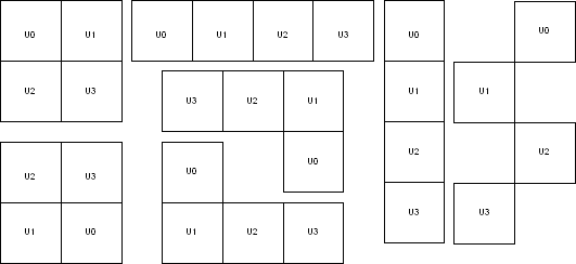
6.14.28.4 Exceptions
None
6.14.28.5 Examples
This example assigns and locks the macro with instance name “multi_tileff/U0 “ at the location X=10, Y=10 by specifying the relative positions of all the macros.
set_multitile_location multi_tileff -location {10 10} \
-tile { multi_tileff/U0 0 0 } \
-tile { multi_tileff/U1 0 1 } \
-tile { multi_tileff/U2 0 2 } \
-tile { multi_tileff/U3 0 3 } -fixed yes
As a result of this command, the four-tile macro placement looks like this:
The second example shows you how to configure a two-tile macro: set_multitile_location multi_tileff -location {10 10} \
-tile { multi_tileff/U0 0 0 } \
-tile { multi_tileff/U1 1 0 }
As a result of this command, the two-tile macro placement looks like this:
6.14.29 set_net_critical
Sets the net criticality, which influences place-and-route in favor of performance.
set_net_criticalcriticality_number [ hier_net_name]+
6.14.29.1 Arguments
- criticality_number
- Sets the criticality level from 1 to 10, with 1 being the least critical and 10 being the most critical. The default is 5. Criticality numbers are used in timing-driven place and route.
- hier_net_name
- Specifies the net name, which can be an AFL (Microchip Flattened Netlist) net name or a
net regular expression using wildcard characters. You must specify at least one net name.
You can use the following wildcard characters in names:
Wildcard
What It Does
\
Interprets the next character as a non-special character
?
Matches any single character
*
Matches any string
[]
Matches any single character among those listed between brackets (that is, [A-Z] matches any single character in the A-to-Z range)
This command must have at least two parameters.
6.14.29.2 Supported Families
Axcelerator
6.14.29.3 Description
Increasing a net’s criticality forces place-and-route to keep instances connected to the specified net as close as possible at the cost of other (less critical) nets.
6.14.29.4 Exceptions
The net names are AFL names, which means they must be visible in Timer and ChipPlanner.
6.14.29.5 Examples
This example sets the criticality level to 9 for all addr nets:
set_net_critical 9 addr*
6.14.30 set_port_block
Sets properties on a port in the block flow. This PDC command applies to only one I/O.
set_port_block -nameportName -remove_ios value -add_interface value]
6.14.30.1 Arguments
- -name portName
- Specify the name of the port.
- -remove_ios value
- Sets whether or not to remove I/Os connected to the specified port from the netlist. The
following table shows the acceptable values for this argument:
Value
Description
yes
Remove I/Os connected to the specified port from the netlist.
no
Do not remove I/Os connected to the specified port from the netlist.
- -add_interface value
- Adds an interface macro each time the fanout of the net connected to the port is greater than the value specified. The value must be a positive integer.
6.14.30.2 Supported Families
IGLOO, ProASIC3, SmartFusion, Fusion, Axcelerator and RTAX
6.14.30.3 Exceptions
- You must import this PDC command as a source file, not as an auxiliary file.
- TRIBUFF and BIBUF macros cannot be removed even if you specify "-remove_ios yes".
- You must enable the block flow before calling this command. To enable the block flow, either select the "Enable block mode" option in the Setup Design dialog box, or use the -block argument in the new_design Tcl command to enable block mode.
6.14.30.4 Examples
This example removes any I/Os connected to portA, excluding TRIBUFF and BIBUF I/Os:
set_port_block -name portA -remove_ios yes
6.14.31 set_preserve
Sets a preserve property on instances before compile, so compile will preserve these instances and not combine them.
set_preserve hier_inst_name
6.14.31.1 Arguments
- hier_inst_name
- Specifies the full hierarchical name of the macro in the netlist to preserve.
6.14.31.2 Supported Families
IGLOO, ProASIC3, SmartFusion, Fusion, and Axcelerator
6.14.31.3 Exceptions
This command is not supported in post compiled designs. If importing a PDC file that includes this command, you must import it as a source file.
6.14.31.4 Examples
In some cases, you may want to preserve some instances for timing purposes. For example, you may want registers to be combined with input of a bibuf and keep the output as it is.
If the outbuf of a bi-directional signal test[1] needs to be preserved while inbuf is required to combine with the registers, use the following PDC commands:
set_io test\[1\] -REGISTER yes set_preserve test\[31\]
If any internal instance is required to be preserved, use the set_preserve command as shown in the following example:
set_preserve top/inst1 top/inst2
6.14.32 unassign_global_clock
Demotes clock nets to regular nets. The unassign_global_clock command is not supported in auxiliary PDC files.
unassign_global_clock -net netname
6.14.32.1 Arguments
- -net netname
- Specifies the name of the clock net to demote to a regular net.
6.14.32.2 Supported Families
IGLOO, ProASIC3, SmartFusion and Fusion
6.14.32.3 Exceptions
You cannot assign “essential” clock nets to regular nets. Clock nets that are driven by the following macros are “essential” global nets: CLKDLY, PLL, and CLKBIBUF.
6.14.32.4 Examples
unassign_global_clock -net globalReset
6.14.33 unassign_local_clock
Unassigns the specified net from a LocalClock region.
unassign_local_clock -net netname
6.14.33.1 Arguments
- -net netname
- Specifies the name of the net to unassign.
6.14.33.2 Supported Families
IGLOO, ProASIC3, SmartFusion, Fusion and Axcelerator
6.14.33.3 Exceptions
This command is not supported in auxiliary PDC files. If importing a PDC file that includes this command, you must import it as a source file.
6.14.33.4 Examples
This example unassigns the net named reset_n from the local clock region:
unassign_local_clock -net reset_n
6.14.34 unassign_macro_from_region
Specifies the name of the macro to be unassigned.
unassign_macro_from_region [region_name] macro_name
6.14.34.1 Arguments
- region_name
- Specifies the region where the macro or macros are to be removed.
- macro_name
- Specifies the macro to be unassigned from the region. Macro names are case sensitive.
You can unassign a collection of macros by assigning a prefix to their names. You cannot
use hierarchical net names from ADL. However, you can use the following wildcard
characters in macro names:
Wildcard
What It Does
\
Interprets the next character as a non-special character
?
Matches any single character
*
Matches any string
[]
Matches any single character among those listed between brackets (that is, [A-Z] matches any single character in the A-to-Z range)
6.14.34.2 Supported Families
IGLOO, ProASIC3, SmartFusion, Fusion and Axcelerator
6.14.34.3 Exceptions
If the macro was not previously assigned, an error message is generated.
6.14.34.4 Examples
unassign_macro_from_region macro21
6.14.35 unassign_net_macros
Unassigns macros connected to a specified net.
unassign_net_macros region_name [net1]+
6.14.35.1 Arguments
- region_name
- Specifies the name of the region containing the macros in the net(s) to unassign.
- net1
- Specifies the name of the net(s) that contain the macros to unassign from the specified region. You must specify at least one net name. Optionally, you can specify additional nets to unassign.
6.14.35.2 Supported Families
IGLOO, ProASIC3, SmartFusion, Fusion and Axcelerator
6.14.35.3 Exceptions
If the region is currently not assigned, an error message appears in the Log window if you try to unassign it.
6.14.35.4 Examples
unassign_net_macros cluster_region1 keyin1intZ0Z_62
6.14.36 unassign_quadrant_clock
unassign_quadrant_clock -net netname
Unassigns the specified net from a QuadrantClock region. If the unassigned net is a clock net, it will not be demoted to a regular net.
6.14.36.1 Arguments
- -net netname
- Specifies the name of the net to unassign from a quadrant clock region.
6.14.36.2 Supported Families
IGLOO, ProASIC3, SmartFusion and Fusion
6.14.36.3 Exceptions
This command is not supported in auxiliary PDC files. If importing a PDC file that includes this command, you must import it as a source file.
6.14.36.4 Examples
This example unassigns the net named qnet_n from the quadrant clock region:
unassign_quadrant_clock -net qnet_n
6.14.37 undefine_region
Removes the specified region. All macros assigned to the region are unassigned.
undefine_region region_name
6.14.37.1 Arguments
- region_name
- Specifies the region to be removed.
6.14.37.2 Supported Families
IGLOO, ProASIC3, SmartFusion, Fusion and Axcelerator
6.14.37.3 Exceptions
To use this command, the region must have been previously defined.
6.14.37.4 Examples
undefine_region cluster_region1
6.14.38 unreserve
Resets the named pins in the current device, so they are no longer reserved. You can then use these pins in your design.
unreserve -pinname "list of package pins"
6.14.38.1 Arguments
- -pinname "list of package pins"
- Specifies the package pin name(s) to unreserve.
6.14.38.2 Supported Families
IGLOO, ProASIC3, SmartFusion, Fusion and Axcelerator
6.14.38.3 Exceptions
None.
6.14.38.4 Examples
unreserve -pinname "F2" unreserve -pinname "F2 B4 B3" unreserve -pinname "124 63"