
6.15 Constraints by File Format: GCF Command Reference
6.15.1 About GCF Files
You can define the following types of constraints in a GCF constraint file:
Only ProASIC devices support GCF Timing commands. Use the SDC timing commands to import timing constraints for ProASIC PLUS devices. All other GCF commands are supported by both ProASIC and ProASIC PLUS devices.
Designer supports the following GCF commands.
|
GCF Placement Command |
Action |
|---|---|
|
Specifies a specific subset of critical ports on a net | |
|
Specifies critical nets and their relative criticality over other critical nets. | |
|
Identifies design I/O ports that have above-normal criticality | |
|
Specifies a location in which no I/O pin should be placed | |
|
Specifies a location in which no cell should be placed | |
|
Initially assigns package pins to I/O ports or sets the location of I/O ports | |
|
Initially sets the location of a cell instance at specified x, y coordinates | |
|
Either assigns package pins to I/O ports or sets the location of I/O ports at a specified location on a device | |
|
Places specific I/O instances into a target rectangular region | |
|
Assigns a cell instance to the specified x,y coordinates | |
|
Creates and assigns memory to a region | |
|
Places all the connected instances, driver, and all the driven instances for the net(s) into the specified rectangle | |
|
Disables the default action that automatically corrects the choice of global assignment to use only the highest fanout nets | |
|
Specifies the name of the constraint file containing the constraints to use | |
|
Specifies the maximum number of global resources to use | |
|
Sets the minimum fan-out a net must have to be considered for automatic promotion to a global | |
|
Classifies the specified nets as global nets | |
|
Classifies nets to avoid automatic promotion to global nets | |
|
Specifies a single spine (LocalClock) or a rectangle of spine region which may encompass more than one spine region | |
|
Prevents buffers and inverters from being removed from the netlist | |
|
Enables you to selectively disable optimization of named hierarchical instances | |
|
Turns on all netlist optimizations (the default mode);enables you to remove buffers and inverters from the netlist | |
|
Sets the maximum fan-out limit on the specified nets when optimizing buffers and inverters |
6.15.2 GCF Syntax Conventions
A ProASIC constraint consists of a statement and an argument, terminated by a semicolon. Statements are not case sensitive. However, cell instance, net, and port names used as arguments may be quoted and are case sensitive. Except for white spaces, all ASCII characters can be used. Comments are allowed in constraints files and must be preceded by two forward slashes (//). Time values are given in nanoseconds. When constraints are duplicated, the last one specified for a specific item overwrites any previous similar constraints already specified for the considered item.
This section describes syntax conventions for notation, user data variables, and comments. Comments begin with double slashes (//) and are terminated by a newline character.
Notation | Description |
|---|---|
item | Represents a syntax item |
item ::= definition | item is defined as definition |
item ::= definition1 ||= definition2 | item is defined as either definition1 or definition2 (Multiple alternative syntax definitions are allowed) |
[ item ] | Item is optional |
{ item } | Item is a list of required items. At least one item must appear. |
KEYWORD | Keywords appear in uppercase characters in bold type for easy identification, but are not case sensitive. |
VARIABLE | Represents a variable and appears in uppercase characters for easy identification |
Notation | Description |
|---|---|
FILEIDENTIFIER | Represents a hierarchical filename. |
IDENTIFIER | Represents the name of a design object. Can be a block, cell instance, net, or port. IDENTIFIERS can use any ASCII character except the white space and the slash (/), which is the hierarchical divider character (see QPATH below). IDENTIFIERS are case sensitive. |
|
POSFLOAT |
Represents a positive real number; for example, 4.3, 1.15, 2.35 |
|
POSNUMBER |
Represents a positive integer; for example, 1, 12, 140, 64. When representing time, POSNUMBER is expressed in nanoseconds (ns) |
|
QPATH |
Represents a hierarchical IDENTIFIER. The levels of the hierarchy are represented by IDENTIFIERS divided by a slash (/). The QPATH hierarchical IDENTIFIER may or may not be quoted |
6.15.3 Placement Constraints
It is possible to use placement constraints to specify block-instance and macro placement. You can specify initial, fixed, region, and macro placements. Also, placement obstructions (locations that are not to be used and thus to be kept empty during placement instances) can be specified.
For example, a constraint that places two connected blocks close together usually improves the timing performance for those blocks. Similarly, a constraint that assigns an I/O pin to a particular net forces the router to make the connection between the driving or receiving cell and the I/O itself.
Like all constraints, placement constraints limit Designer’s freedom when processing the design. For instance, assigning a fixed location makes that location unavailable during placement optimization. Such removal usually limits the program’s ability to produce a chip-wide solution.
6.15.4 Macro
Defines the locations of a sub-design as a macro so that you are able to reuse this placement in different instantiations of the sub-design.
macro name (x1, y1 x2, y2) {macro_statements}
6.15.4.1 Arguments
- name
- Specifies the macro name identifier
- x1, y1
- Specifies the lower-left coordinate of the macro.
- x2, y2
- Specifies the upper-right coordinate of the macro.
- macro_statements
- Any of the following statements:
- set_location (x, y) hier_inst_name;
- set_initial_location (x, y)hier_inst_name;
- set_empty_location (x, y);
- macro_name [transformations];
- Where hier_inst_name is the hierarchical name of the instance of the sub-design, x, y is
the final location of the lower-left corner of the macro after all transformations have
been completed, macro_name is the name of previously defined macro, and transformations
are optional, and any of the following in any order:
- flip lr - flip cell from left to right
- flip ud - flip cell from up to down
- rotate 90 cw - rotate 90° clockwise
- rotate 270 cw - rotate 270° clockwise
- rotate 90 ccw - rotate 90° counter-clockwise
- rotate 180 ccw - rotate 180° counter-clockwise
- rotate 270 ccw - rotate 270° counter-clockwise
6.15.4.2 Supported Families
ProASIC
6.15.4.3 Description
The macro constraint must precede the corresponding set_location that places the macro in the GCF file(s) as in the following example:
macro mult (1,1 6,6) { set_location...
}
Nested macros are not allowed. The location statements inside a macro definition must refer to individual cell instances and not to complete sub-designs.
6.15.4.4 Exceptions
None
6.15.4.5 Examples
set_location (3,3) a/b mult flip lr; set_initial_location (3,3) a/b mult flip lr;
6.15.5 Package Pin and Pad Location
Generally, you are concerned with the mapping of signals (ports) to the pins of the selected package. However, you may want to control the allocation of signals to particular pads. This is accomplished by assigning ports to the pad location rather than to the package pin. Because all pads are pre-bonded to package pins, the effect is to assign ports to package pins, with the emphasis on pad location rather than package pin.
Pad location is described by the letters N (North), S (South), E (East) or W (West) followed by a space and a number. This location code determines the direction and offset of the pad with respect to the die.
The top edge of the viewer contains the North pads and the right edge contains the East pads. The number refers to the pad position along its edge. For example, N 48 corresponds to the 48th pad along the North edge of the die. The figure below shows the numbering system used for pad location.
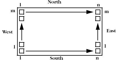
Figure 17 · Pad Location
6.15.6 net_critical_ports
net_critical ports hier_net_name instance_port_name [ , instance_port_name ];
Defines a subset of critical ports on a net. The resulting netlist contains a buffer in the origin net, together with the critical ports. The inserted buffer drives the remaining connections on the original net.
6.15.6.1 Arguments
- hier_net_name
- Specifies the name of the hierarchical net(s).
- instance_port_name
- Specifies the name of the ports on the net(s).
6.15.6.2 Supported Families
ProASIC PLUS and ProASIC
6.15.6.3 Exceptions
None
6.15.6.4 Examples
The following example identifies two inputs of the net /u1/u2/net1 that are more critical than all other connections on that net. All other connections on the net will be buffered with a BUF cell that will be placed in a tile to reduce fanout delay on the specified inputs:
net_critical_ports /u1/u2/net1 nandbk1.A sigproc.C;
6.15.7 set_critical
Specifies critical nets and their relative criticality over other critical nets.
set_critical criticality_numberhier_net_name
[,hier_net_name…];
6.15.7.1 Arguments
- criticality_number
- Sets the criticality level from 1 to 5, with 1 being the least critical and 5 being the most critical. The default is 1. Criticality numbers are used in timing-driven place and route.
- hier_net_name
- Specifies the full hierarchical name of the net(s).
6.15.7.2 Supported Families
ProASIC PLUS and ProASIC
6.15.7.3 Exceptions
None
6.15.7.4 Examples
The following example sets the timing of u1/u2/ net1 more critical than u1/u2/net5 and u1/u2/net3:
set_critical 5 /u1/u2/net1; set_critical 2 /u1/u2/net5, u1/u2/net3;
6.15.8 set_critical_port
Identifies design I/O ports that have above-normal criticality.
set_critical_port criticality_number signal_name
[,signal_name…];
6.15.8.1 Arguments
- criticality_number
- A number from 1 to 5 that is relative in criticality to other critical I/O signals, from least (1) to most critical (5). The default is 1.
- signal_name
- Specifies the name of a user-defined signal associated with a specific I/O pin on the port.
6.15.8.2 Supported Families
ProASIC PLUS and ProASIC
6.15.8.3 Exceptions
None
6.15.8.4 Examples
The following example sets all nets associated with device ports IOBus[3] and IOBus[5] to criticality number 3:
set_critical_port 3 IOBus[3], IOBus[5];
6.15.9 set_empty_io
set_empty_io { package_pin| pad_location};
Specifies a location in which no I/O pin should be placed. The location can be specified by side and offset or by name.
6.15.9.1 Arguments
- package_pin
- The symbolic name for the pin.
- pad_location
- Specifies the location of the pad in the layout.
6.15.9.2 Supported Families
ProASIC PLUS and ProASIC
6.15.9.3 Exceptions
None
6.15.9.4 Examples
The following example forces pin B5 and the pin associated with the fourth tile on the North side to be empty:
set_empty_io B5, (N,4);
6.15.10 set_empty_location
Specifies a location in which no cell should be placed.
set_empty_location (x ,y); set_empty_location (xbl ,ybl xtr ,ytr);
6.15.10.1 Arguments
- x, y
- Specifies the tile coordinates for the empty cell location.
- xbl ,ybl xtr ,ytr
- Specifies the tile coordinates for the bottom-left and top-right corner of the region. Note: Only white spaces are allowed between the coordinates.
6.15.10.2 Supported Families
ProASIC PLUS and ProASIC
6.15.10.3 Exceptions
None
6.15.10.4 Examples
The following example informs the placement program that location (3, 7) is unavailable for cell placement:
set_empty_location( 3 ,7);
set_empty_location(113 ,1 60 ,80 );
6.15.11 set_initial_io
set_initial_io { package_pin| pad_location} io_port_name
[, io_port_name , … ];
Initially assigns package pins to I/O ports or sets the location of I/O ports at a specified side of a device. The placer can reassign or relocate the cells during place-and-route.
6.15.11.1 Arguments
- package_pin
- A package pin number for a specified I/O cell. If you use package_pin, only one io_port_name argument is allowed (required if no pin location is given).
- pad_location
- A pad location number on the chip. It constrains the pin location of a specified I/O cell to a specific pad location on the chip. Only one io_port_name argument is allowed. You can specify multiple, comma-separated ports only when they are assigned to a location.
- io_port_name
- The name of the I/O port to assign to the specified package pin.
6.15.11.2 Supported Families
ProASIC PLUS and ProASIC
6.15.11.3 Exceptions
None
6.15.11.4 Examples
The following example initially places the I/O associated with net in3 to package pin A11:
set_initial_io A11 in3;
The next example initially places the I/O associated with net in4 on the fourth tile:
set_initial_io (1,4) in4;
6.15.12 set_initial_location
set_initial_location ( x, y) hier_inst_name;
Initially sets the location of a cell instance at specified x, y coordinates. The placer can relocate the cell instance during place-and-route.
6.15.12.1 Arguments
- x, y
- Specifies the tile coordinates for the location of a specified cell instance.
- hier_inst_name
- Specifies the hierarchical path to a cell instance.
6.15.12.2 Supported Families
ProASIC PLUS and ProASIC
6.15.12.3 Exceptions
None
6.15.12.4 Examples
set_initial_location (43,105) bk3/fp5/nand3_4;
6.15.13 set_io
Either assigns package pins to I/O ports or sets the location of I/O ports at a specified location on a device. This hard constraint cannot be overruled by the placer. This constraint also may have an impact on the timing results of a design.
set_io {pinName |location_Definition};
6.15.13.1 Arguments
- pinName
- Specifies the name of a pin to assign to a port.
- location_Definition
- Specifies the location of the I/O port.
6.15.13.2 Supported Families
ProASIC PLUS and ProASIC
6.15.13.3 Exceptions
If a hard constraint is not suitable, use the set_initial_io constraint.
6.15.13.4 Examples
set_io A9 in1; set_io (2,22) in2;
6.15.14 set_io_region
set_io_region (x1,y1 x2, y2) p1 [, p2, p3, .... , pn] ;"
Enables you to place specific I/O instances into a target rectangular region. The global I/Os are excluded from this constraint.
6.15.14.1 Arguments
- x1, y1 x2, y2
- Specifies the lower-left and upper-right corners of the rectangle that define the region.
- p1... pn
- Specifies one or more I/O instance names or ports.
6.15.14.2 Supported Families
ProASIC PLUS and ProASIC
6.15.14.3 Exceptions
None
6.15.14.4 Examples
Multiple instances or ports must be separated by commas as shown in the following example:
set_io_region (0,41 0,48) "acc[3]", "acc[4]";
6.15.15 set_location
set_location (x, y ) hier_inst_name ; set_location (xbl ,ybl xtr ,ytr) hier_inst_name/*;
Assigns a cell instance to the location specified by the x,y coordinates. The placer cannot relocate the cell instance during place-and-route.
6.15.15.1 Arguments
- x, y
- Specifies the tile coordinates for the location of a cell.
- hier_inst_name
- Specifies the hierarchical path to a cell instance.
- xbl ,ybl xtr ,ytr
- Specifies the tile coordinates for the bottom-left and top-right corner of the region.
6.15.15.2 Supported Families
ProASIC PLUS and ProASIC
6.15.15.3 Exceptions
None
6.15.15.4 Examples
set_location (1,15) u4/u3/nand3_4;
set_location (1,1 32,32) datapath/*;
6.15.15.5 set_location macro call
set_location (x, y) hier_subdesign_inst_name macro_name [transformations];
This statement has been extended to allow you to place a sub-design instance by calling its macro and then applying a translation and rotation.
where
hier_subdesign_inst_name is the hierarchical name of the instance of the sub-design; (x, y) is the final location of the lower left corner of the macro after all transformations have been completed; macro_name is the name of the previously defined macro; transformations are optional, and any of the following in any order:
- flip lr - flip cell from left to right
- flip ud - flip cell from up to down
- rotate 90 cw - rotate 90 ° clockwise
- rotate 180 cw - rotate 180 ° clockwise
- rotate 270 cw - rotate 270 ° clockwise
- rotate 90 ccw - rotate 90 ° counter-clockwise
- rotate 180 ccw - rotate 180 ° counter-clockwise
6.15.16 set_memory_region
Creates a region and assigns memory to it.
set_memory_region (x1,y1 x2,y2) memory1_name [,...,memoryn_name];
6.15.16.1 Arguments
- (x1,y1 x2,y2)
- The coordinates x1 and y1 specify the bottom-left corner, while x2 and y2 specify the top-right corner of the rectangle that defines the region in which the memory macros will be assigned. The macros are constrained to this region.
- memory1_name,...
- Specifies the memory macro(s) to assign to the region. Macro names are hierarchical names in the user netlist. You can use wildcards in macro names. The wildcard character (*) matches any string.
6.15.16.2 Supported Families
ProASIC PLUS and ProASIC
6.15.16.3 Description
You can only assign names of memory macros to the region. Do not specify names of individual tiles. For cascaded memory, the set_memory_region constraint applies to the whole cascaded block, even if your statement mentions only one macro out of the whole cascaded block.
6.15.16.4 Exceptions
None
6.15.16.5 Examples
set_memory_region (1,101 32,101) M1/U0;
set_memory_region (1,101 48,101) M1/U0,M1/U1;
set_memory_region (1,101 128,101) M1/U*;
You can also use set_net_region and use_global to assign memory to regions.
Additionally, you can use the MultiView Navigator (MVN) to create regions that include memory. MVN regions can span core, I/O, and/or memory.
6.15.17 set_net_region
Places all the connected instances, driver, and all the driven instances for the net(s) into the specified rectangle.
set_net_region (x1,y1 x2,y2) <net_name_wildcard>;
6.15.17.1 Arguments
- (x1,y1 x2,y2)
- The coordinates x1 and y1 specify the bottom-left corner, while x2 and y2 specify the top-right corner of the rectangle that defines the region. The nets are constrained to this region.
- net_name_wildcard
- Specifies the net(s) to assign to the region. You can use wildcards in net names. The wildcard character (*) matches any string.
6.15.17.2 Supported Families
ProASIC PLUS and ProASIC
6.15.17.3 Description
This command puts the region constraint on all the connected instances, which will be processed by the placer. Only white spaces are allowed between the coordinates.
The RAMs and I/Os are assigned to the LocalClock region unless the Compile option “Include RAM and I/O in Spine and Net Regions” is cleared. For designs created with v5.1 or earlier, this option is cleared by default. See "Compile Options" in the online help for more information.
6.15.17.4 Exceptions
None
6.15.17.5 Examples
set_net_region (1,101 32,101) addr*;
6.15.18 About Global Resource Constraints
Each ProASIC and ProASIC PLUS device includes four global networks that have access to every tile. These four global networks provide high speed, low skew routing resources to signals such as clocks and global resets.
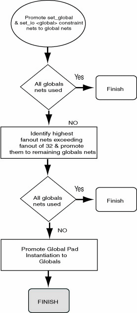
Once the netlist is imported, Designer sets global resource parameters and promotes the highest fanout nets to the remaining global resources unless the dont_fix_globals statement has been specified in a constraint file.
Note: Note: When using the dont_fix_globals statement, global assignments made in the constraint files and design netlist will be honored (the constraint file entries will take precedence).
These global resource parameters can be supplemented by including global resource constraints in a constraint file. Global resource constraints can define which signals are assigned to global resources and which signals cannot be promoted to global resources. Global resource constraints can also override the default action that selects high fanout nets for use by the global resources.
6.15.18.1 Priority Order for Global Promotion
While assigning signals to global resources, Designer considers this information in the following priority:
- The set_global and set_io statements (instances of those global cells, which cannot be demoted)
- Nets with the highest potential fan-out above 32 (after removal of all buffers and inverters)
- Global cell instantiation in a netlist (global cells which can be demoted)
By default, a net with a fan-out of less than 32 will not be promoted to global automatically unless the set_global or set_io constraint statements is used for this net. You can override this threshold of 32 by using the set_auto_global_fanout constraint statement.
6.15.18.2 dont_fix_globals
dont_fix_globals;
Disables the default action that automatically corrects the choice of global assignment to use only the highest fan-out nets.
6.15.18.2.1 Arguments
None
6.15.18.2.2 Supported Families
ProASIC PLUS and ProASIC
6.15.18.2.3 Exceptions
None
6.15.18.2.4 Examples
If you do not want the Designer software to automatically assign the highest fan-out nets to the available global resources but respect your choice of global nets instead, then include the following statement in a constraint file:
dont_fix_globals;
6.15.18.3 read
Specifies the name of the constraint file containing the constraints to use.
read [ -eco] [ -initial] file ;
6.15.18.3.1 Arguments
- -eco
- Specifies that the constraint file is to be read in eco (engineering change order) mode. In this mode, no errors will be reported when certain nets or instances are not found in the design. Instead a warning is generated.
- -initial
- Specifies that the constraint file is to be read in initial mode. In this mode, all fixed location statements will be interpreted as initial locations instead.
- file (required)
- The name of the constraint file, surrounded by double quotes.
6.15.18.3.2 Supported Families
ProASIC PLUS and ProASIC
6.15.18.3.3 Description
A constraint file can contain multiple read statements. For example, you can put pin assignments in one file, optimization constraints in another, placement constraints in yet another, and read them all in through a master constraint file.
6.15.18.3.4 Exceptions
None
6.15.18.3.5 Examples
The following example instruct the Designer software to use constraints from the GCF files pinmap.gcf and decoder.gcf. A full path specification is given for pinmap.gcf. The file decoder.gcf has no path specification and is assumed to be in the design working directory.
read "/net/aries/designs/pinmap.gcf"; read "decoder.gcf";
6.15.18.4 set_auto_global
set_auto_global number;
Specifies the maximum number of global resources to use. The Designer software assigns global resources to high fan-out signals automatically.
6.15.18.4.1 Arguments
- number
- The maximum number of global resources to use in your design. If you specify a number that exceeds the actual number of global resources available in the device, the Designer software ignores the statement. If you specify 0, no automatic assignment to global resources occurs.
6.15.18.4.2 Supported Families
ProASIC PLUS and ProASIC
6.15.18.4.3 Exceptions
None
6.15.18.4.4 Examples
The following example specifies that of the possible four global nets available, the Designer software can automatically promote only two high fan-out nets:
set_auto_global 2;
6.15.18.5 set_auto_global_fanout
Sets the minimum fan-out a net must have to be considered for automatic promotion to a global.
set_auto_global_fanout number;
6.15.18.5.1 Arguments
- number
- The minimum fan-out for a net. The default number is 32.
6.15.18.5.2 Supported Families
ProASIC PLUS and ProASIC
6.15.18.5.3 Exceptions
None
6.15.18.5.4 Examples
For example, the following statement determines that a net must have a fan-out of at least 12 before Designer considers it for automatic promotion to a global resource.
set_auto_global_fanout 12;
6.15.18.6 set_global
Classifies the specified nets as global nets.
set_global hier_net_name [, hier_net_name ...];
6.15.18.6.1 Arguments
- hier_net_name
- Specifies the name of the hierarchical net(s).
6.15.18.6.2 Supported Families
ProASIC PLUS and ProASIC
6.15.18.6.3 Exceptions
None
6.15.18.6.4 Example
set_global u1/u3/net_clk, u3/u1/net_7;
6.15.18.7 set_noglobal
set_noglobal hier_net_name[ , hier_net_name… ];
Classifies nets to avoid automatic promotion to global nets. If the net was previously assigned to a global resource, this statement will demote it from that resource.
6.15.18.7.1 Arguments
- hier_net_name
- Specifies the name of the hierarchical net(s).
6.15.18.7.2 Supported Families
ProASIC PLUS and ProASIC
6.15.18.7.3 Exceptions
None
6.15.18.7.4 Example
set_noglobal u2/u8/net_14;
6.15.18.8 use_global
Specifies a single spine (LocalClock) or a rectangular spine region which may encompass more than one spine.
use_global spine <net_name>;
6.15.18.8.1 Arguments
- spine
- Specifies one of the spines: T1 to T<n> or B1 to B<n>.
- net_name
- Specifies the name of a net.
6.15.18.8.2 Supported Families
ProASIC PLUS and ProASIC
6.15.18.8.3 Exceptions
None
6.15.18.8.4 Example
If you specify the spine rectangle as B1, T3, the driven instances of the given net get a region constraint which encloses the rectangle, including the spine rectangle B1, T1, B2, T2, B2, T3.
use_global B1, T3 <net_name>;
The constraint tries to place the driver as close to the center of the rectangle as possible.
The RAMs and I/Os are assigned to the LocalClock region unless the Compile option “Include RAM and I/O in Spine and Net Regions” is cleared. For designs created with v5.1 or earlier, this option is cleared by default. See "Compile Options" in the online help for more information.
You can specify the following type of rectangles:
- Bn, Bm : n<=m will mean Bn, Bn+1, ... Bm
- Tn, Tm : n<=m will mean Tn, Tn+1, ... Tm
- Bn, Tm : n<=m will mean Bn, Tn, Bn+1,Tn+1 ... Bm, Tm
- Tn, Bm : n<=m will mean Bn, Tn,
Bn+1,Tn+1 ... Bm, Tm The following table summarizes the available spines.
Table 6-8. Global Spine Usage Device
Spine
A500K050
T1 to T3
B1 to B3
A500K130
T1 to T5
B1 to B5
A500K180
T1 to T6
B1 to B6
A500K270
T1 to T7
B1 to B7
APA075
T1 to T3
B1 to B3
APA150
T1 to T4
B1 to B4
APA300
T1 to T4
B1 to B4
APA450
T1 to T6
B1 to B4
APA600
T1 to T7
B1 to B7
APA750
T1 to T8
B1 to B8
APA1000
T1 to T11
B1 to B11
T1 and B1 are the leftmost top and bottom global spines, respectively.
6.15.19 Netlist Optimization Constraints
Netlist optimization attempts to remove all cells from a netlist that have no effect on the functional behavior of the circuit. This reduces the overall size of a design and produces faster place-and-route times. This optimization is based on the propagation of constants and inverter pushing and takes advantage of inverted inputs of the basic logic elements.
Netlist optimization can be controlled by including netlist optimization constraints in constraint files submitted to Designer.
By default, all optimizations will be performed on the netlist. To control the amount of optimization that takes place, netlist optimization constraints can be used. Netlist optimization constraints can turn off all optimizations or disable the default action that allows all optimizations to limit the type of optimizations performed. The constraints can also define a maximum fanout to be allowed after optimizations are performed and isolate particular instances and hierarchical blocks from the effect of optimization.
After completion of netlist optimization, the design is a functionally identical representation of the design produced internally for use by Designer. View the design’s layout after successful placement and routing. After optimization, a number of instances that do not contribute to the functionality of the design may have been removed.
To keep the SDF file consistent with the original input netlist, deleted cells are written with zero delay so that back-annotation is performed transparently.
6.15.19.1 dont_optimize
Prevents buffers and inverters from being removed from the netlist.
dont_optimize [option];
6.15.19.1.1 Arguments
- [option ]
- Specifies the netlist optimization option to turn off and preserve.
Option
Description
buffer
Prevents buffers from being removed from the design
inverter
Prevents inverters from being removed from the design
const
Replaces all logical elements with one or more inputs connected to a constant (logical "1" or "0") by the appropriate logic function. If the replacement logic function is identified as an inverter or buffer, that element is removed.
dangling
Removes all cells driving unconnected nets
6.15.19.1.2 Supported Families
ProASIC PLUS and ProASIC
6.15.19.1.3 Description
This statement does not optimize your buffers or inverters; instead, it prevents them from being removed. When followed by one or more of the netlist optimization options, this statement turns off the named option (and preserves it).
If you have buffers or inverters that are connected to global nets, promoted global nets, or spine nets, this command is ignored and buffers and inverters are removed. To avoid removing them, use the dont_touch option.
6.15.19.1.4 Exceptions
None
6.15.19.1.5 Examples
dont_optimize buffer inverter;
6.15.19.2 dont_touch
Enables you to selectively disable optimization of named hierarchical instances.
dont_touch {hier_instance_name [hier_instance_name...];
6.15.19.2.1 Arguments
- hier_instance_name [hier_instance_name ... ]
- Specifies the name of the hierarchical instance(s) for which you want to disable optimization.
6.15.19.2.2 Supported Families
ProASIC PLUS and ProASIC
6.15.19.2.3 Description
You can use the wildcard character (*) to isolate all sub-blocks under the named block. If you use this constraint, any instances (including buffers and inverters that are connected to global nets, promoted global nets, and spine nets) stay intact.
6.15.19.2.4 Exceptions
Use “dont_touch” with instance names only. You cannot use this constraint with net names.
6.15.19.2.5 Examples
The statement in this example will enable only the buffer and inverter optimization types and optimization will be done on all instances except those contained in the block called /U1/myblock.
dont_touch /U1/myblock/*;
6.15.19.3 Optimize
Turns on all netlist optimizations (the default mode). When followed by one or more of the netlist optimization types, this statement enables only the named optimization(s).
optimize [{ option}];
6.15.19.3.1 Arguments
- [{ option }]
- Specifies the netlist optimization option to turn on.
Option
Description
Removes all buffers in the design, provided you have not exceeded the maximum fan-out
inverter
Removes all inverters in the design, provided you have not exceeded the maximum fan-out
const
Replaces all logical elements with one or more inputs connected to a constant (logical “1” or “0”) by the appropriate logic function. If the replacement logic function is identified as an inverter or buffer, that element is removed.
dangling
Recursively removes all cells driving unconnected nets
6.15.19.3.2 Supported Families
ProASIC PLUS and ProASIC
6.15.19.3.3 Exceptions
None
6.15.19.3.4 Examples
optimize buffer inverter;
6.15.19.4 set_max_fanout
Sets the maximum fan-out limit on the specified nets when optimizing buffers and inverters.
set_max_fanout NUMBER net_name_wildcard;
6.15.19.4.1 Arguments
- NUMBER net_name_wildcard
- Specifies the maximum fan-out limit on the specified net(s) during optimization.
6.15.19.4.2 Supported Families
ProASIC PLUS and ProASIC
6.15.19.4.3 Description
The set_max_fanout constraint is optimized to accept individual net names. If you specify a net name, the set_max_fanout constraint applies only to the named net or nets and not to the entire design.
The buffers and inverters are not removed if the fan-out for the given net exceeds the given limit. If no net name is given, then the command is applied to all the nets in the design. The net name can be a simple net or a name having wildcard characters.
6.15.19.4.4 Exceptions
None
6.15.19.4.5 Examples
set_max_fanout 15 testNet*;
6.15.20 About Delay Constraint Files (DCF)
Delay constraint information can be described in a *.dcf file and imported into Designer. Because the DCF language was developed to interact directly with the Timer tool and is therefore not a recommended method.
DCF files are only valid with earlier Antifuse families such as eX, SX-A, and SX. Although they are supported in eX and SX-A, Microchip recommends that you use SDC files for all your constraints.
DCF files are platform dependent. If you transfer from PC to UNIX or vice-versa, you must manually translate carriage-returns (unix2dos, dos2unix, or via ftp). PC text files have an extra character for carriage returns compared to UNIX text files.
| Categories | Action |
|---|---|
| global_clocks | Describes the clock waveforms from the global clock distribution network; local clocks, such as gated clocks, are not directly supported |
| max_delays/min_delays | Describes max/min delays |
| io_arrival_times | Defines the arrival time to an input port |
| global_stops | Defines pins in don't care or false path |
| pin_loads | Defines the capacitance loading on package pins |
6.15.20.1 DCF Syntax Rules
DCF Syntax Rules
The syntax rules for DCF are listed below. Note that these rules cannot be used as a parsing grammar. Terminal symbols are in upper case. Non-terminal symbols, which are enclosed with <>, are in lower case. Symbols enclosed with [] are optional. The symbol | separates alternatives.
<DCF> =
<sec_def_name>
<sec_io_arr>
<sec_min_del>
<sec_max_del>
<sec_clk>
<sec_global_stop>
<sec_def_name> =
SECTION TOP_LEVEL_DEF_NAME <stop>
<variable>. END <stop>
<sec_io_arr> =
SECTION IO_ARRIVAL_TIMES <stop>
[<io_arr_clauses>]
END <stop>
<io_arr_clauses> = <io_arr_clause> | <io_arr_clause> <io_arr_clauses>
<io_arr_clause> = [<number>:] <number> <timeunit> <io_list>.
<io_list> = <io> | <io> <io_list>
<io> = INPAD | OUTPAD| <variable>
<sec_max_del> =
SECTION MAX_DELAYS <stop>
<delay_clauses> END <stop>
<sec_min_del> =
SECTION MIN_DELAYS <stop>
<delay_clauses> END <stop>
<delay_clauses> = <delay_clause> | <delay_clause> <delay_clauses>
<delay_clause> =
DELAY <time>; SOURCE <source_list>; SINK <sink_list>; [STOP <stop_list>]; [PASS <pass_list>].
<source_list> = {<sources>} [EXCEPT {<sources>}]
<sources> = INPAD | CLOCKED | <name_list>
<name_list> = <variable> | <variable> <name_list>
<sink_list> = {<sinks>}[EXCEPT {<sinks>}]
<sinks> = OUTPAD | GATED | <name_list>
<stop_list> = {<name_list>} [EXCEPT {<sinks>}]
<pass_list> = {<name_list>} [EXCEPT {<sinks>}]
<sec_clk> =
SECTION GLOBAL_CLOCKS <stop>
[<waveform_clauses>] [<relational_clauses>] END <stop>
<waveform_clauses> = <waveform_clause> | <waveform_clause> <waveform_clauses>
<waveform_clause> = WAVEFORM <variable> RISE <time> FALL<time> PERIOD <time> [EXCEPT SOURCE {macrolist}] [EXCEPT SINK {macrolist}].
<relational_clauses> = <check_clause> | <check_clause> <check_clauses>
<check_clause> =
MULTICYCLE <variable> SOURCE CYCLE<value> [EXCEPT <name_list>] [; DESTINATION <clkname> CYCLE<value> <clkname> CYCLE<value> [EXCEPT<name_list>]].
<clkname> = <clockMacro>
<time> = <number> <unit>
<number> = <int>
<stop> =. | /* NULL */
<unit> = NS | MS | PS
<variable> = same as variable in C language.
<int> = same as int in C language. sec_global_stops> =
Section GLOBAL_STOPS.
{<pinNameList>}. End.
<sec_pin_loads> = Section PIN_LOADS.
<pinLoadClauses> End.
<pinLoadClauses> = <pinLoadClause> | <pinLoadCause>l<pinLoadClauses>]
<pinLoadClause> = <number> <capUnit> [TTL | CMOS] <pinNameList>.
<capUnit> = PF | NF | UF | MF
6.15.20.2 io_arrival_times
6.15.20.2.1 SECTION IO_ARRIVAL_TIMES
Use the IO_ARRIVAL_TIMES section to define the arrival time to an input port.
[early_arrival_time:] late_arrival_time timeunit {source_io_list} EXCEPT {source_io_list}.
6.15.20.2.2 Arguments
- {early, late}_arrival_time
- Signal arrival time relative to the reference time.
- source_io_list
- An INPAD or primary input pin.
The section IO_ARRIVAL_TIMES can be empty. For example,
SECTION IO_ARRIVAL_TIMES. END.
is entirely equivalent to
SECTION IO_ARRIVAL_TIMES.
0 0 {INPAD}. END
6.15.20.3 max_delays/min_delays
6.15.20.3.1 SECTION MAX_DELAYS/MIN_DELAYS
Use the MAX_DELAYS and MIN_DELAYS section to specify the maximum and minimum delays.
DELAY value timeunit; SOURCE {source_name_list}; SINK {sink_name_list}; [STOP
{stop_name_list}]; [PASS {bypass_name_list}].
6.15.20.3.2 Arguments
- DELAY value
- Specifies an integer.
- timeunit
- Allows {PS, NS, US}.
- source_name_list
- A list of signal sources. It can be one of the following: a macro output pin, macro name, or primary input.
- sink_name_list
- A list of signal destinations. It can be a name of a macro or a primary output.
- stop_name_list
- The list of pin names through which further propagation of signals will not be considered. This allows you to eliminate certain paths from consideration.
- bypass_name_list
- The list of latches which are allowed to be intermediate path points. By default, latches are considered to be sinks or path terminals.
- INPAD/OUTPAD/GATED
- Valid values for any of the lists, such as source_name_list or stop_name_list.
Normally there is no need to specify any timing requirements from any source to any sink clocked by an external global clock. This timing requirement can be generated automatically from the GLOBAL_CLOCK specifications and the sequential elements setup and hold times. For example, the timing constraint from a primary input to a sequential element can be derived from the sequential elements clocking waveform and the signal arrival time of the primary input.
A problem exists when two different internally-generated clock signals interact. This is due to the unpredictable and unknown skew between the two clock networks because of the routing delays from:
PAD >> internalMacro >> CLKINT
where CLKINT is the input pin of the global clock distribution network. The automatically generated path constraints will not incorporate the skew between the two clocks. In such cases, the path constraints should be expressed explicitly using the MAX/MIN_DELAYS section.
The most stringent timing constraint dominates. Hence, all general constraints should be looser than the specific constraints. For example, in the following example, the 26.0ns constraint dominates the 42.0ns constraint:
DELAY 42.0 ns SOURCE INPAD SINK OUTPAD.
DELAY 26.0 ns SOURCE {$1I23:Q $1I24:Q} SINK {ack_0}.
If the general constraint is tighter than the specific constraint, the specific constraint will effectively become a no-operation. In the following example, the looser constraint of 42.0ns has no effect since the general constraint of 26.0ns dominates.
DELAY 26.0 ns SOURCE INPAD SINK OUTPAD.
DELAY 42.0 ns SOURCE {$1I23:Q $1I24:Q} SINK {ack_0}.
The section MAX_DELAYS can be empty if there are no purely combinatorial paths from external sources to external sinks, and if every sequential element in the design is clocked by an external global clock. In this case, the timing constraints are generated automatically using the information in the GLOBAL_CLOCK section. Likewise, the MIN_DELAYS section can be empty.
One final word about external/internal sinks and sources with regard to the flip-flops and/or latches in the IOs: these flip-flops act as internal, not external, sources/sinks.
6.15.20.4 global_clocks
6.15.20.4.1 SECTION GLOBAL_CLOCKS
WAVEFORM clkname RISE value FALL value PERIOD value [EXCEPT SOURCE {sequential list }| EXCEPT SINK{sequential list}].
Use the GLOBAL_CLOCKS section to describe the clock waveforms from the global clock distribution networks. Local clocks, such as gated clocks, are not directly supported. The clock waveforms are used to generate the timing constraints of the paths between two sequential elements. To allow more user control when clocks interact, there are provisions to specify the clock period transitions, which should be considered. By default, the closest transitions are used when two clocks interact. The clock waveform specification has the following format:
6.15.20.4.2 Arguments
- clkname
- Specifies the name of the macro driving the clock network.
- RISE/FALL/PERIODvalue
- Specify the value as either an integer or a floating point number followed by an unit selected from {NS, US, PS}. The default time unit is 0.1ns.
- EXCEPT {SOURCE|SINK} {sequential list}
- Specify the list of sequential elements which should not be included as endpoints in the automatically generated paths involving sequential elements.
6.15.20.5 MULTICLOCK
Use the MULTICLOCK specification to specify which clock periods should be considered during the generation of the path constraints involving sequential elements. The default specification is to consider only the closest clock periods of the SOURCE and DESTINATION clocks. This specification has the following syntax:
MULTICYCLE SOURCE clkA CYCLE value EXCEPT {seqlist}; DESTINATION clkB CYCLE value EXCEPT
{seqlist}.
MULTICYCLE SOURCE clkA CYCLE value EXCEPT {seqlist}.
6.15.20.5.1 Arguments
- clkA/clkB
- The name of the macro driving the clock network.
- EXCEPT {seqlist}.
- By default all sequential elements clocked by the clock driver are included. The EXCEPT seqlist is a list of all the sequential elements or specific pins to be excluded.
- CYCLE value
- By default, the closest transitions are considered. CYCLE provides the ability to use transitions from one or more clock periods past the closest transition. CYCLE zero indicates the closest transitions. CYCLE one skips the closest set of transitions and uses the next set of transitions. The term cycle is used to avoid confusion with the term period in the clock waveform specification. This allows you to specify a cycling-stealing clocking regime.
6.15.20.6 global_stops
6.15.20.6.1 SECTION GLOBAL_STOPS
{<pinNameList>}. End.
Use the GLOBAL_STOPS section to disable dont care/false paths by preventing the specified pins from being used in ANY timingcritical paths. Any path involving pins that appear in this section should be removed from consideration.
6.15.20.7 pin_loads
6.15.20.7.1 SECTION PIN_LOADS
Use the PIN_LOADS section to define the capacitance loading and logic (TTL/CMOS) at a package pin. The default logic family is TTL.
capValue capUnit [TTL/CMOS]{[macList|pinList]} [EXCEPT {}].
6.15.21 About PIN Files
PIN files are only valid with earlier Antifuse families such as eX, SX-A, and SX. Although PIN files are supported in Axcelerator, Microchip recommends that you use PDC files instead to set pin locations for Axcelerator.
You can describe the location of a pin in a *.PIN file and import it into Designer. PIN files contain two commands: DEF and PIN.
|
Commands |
Description |
|---|---|
|
DEF |
Define top-level design entity |
|
PIN |
Define I/O location |
6.15.21.1 DEF
Syntax:
DEF <design_name>
The following example defines top-level structure as TARG32_WRP.
DEF TARG32_WRP.
6.15.21.2 PIN
Syntax:
PIN <pin_name>;PIN:<package_pin_number>.
The following example assigns signal RST to package pin 156.
PIN RST; PIN:156.