
6.3 Basic Concepts
This section describes the basic concepts used in this document.
6.3.1 Designer Naming Conventions
The names of ports, instances, and nets in an imported netlist are sometimes referred to as their original names. Port names appear exactly as they are defined in a netlist. For example, a port named A/B appears as A/B in ChipPlanner, PinEditor, and I/O Attribute Editor in MultiView Navigator. Instances and nets display the original names plus an escape character (\) before each backslash (/) and each slash (\) that is not a hierarchy separator. For example, the instance named A/\B is displayed as A\/\\B.
Following are Designer's naming conventions by device.
6.3.1.1 SmartFusion, Fusion, ProASIC3, and Axcelerator
The following components use the Tcl-compliant original names:
- PDC reader/writer
- SDC reader/writer
- Compile report
- SDF/Netlist writer for back annotation
- MultiView Navigator tools: NetlistViewer, PinEditor, ChipPlanner, and I/O Attribute Editor
- SmartTime
- SmartPower
6.3.1.2 ProASIC, ProASIC PLUS, SX-A, and eX
The following components use the Tcl-compliant original names:
- SDC reader/writer
- MultiView Navigator tools: NetlistViewer, PinEditor, ChipPlanner, and I/O Attribute Editor
- SmartTime
GCF follows the netlist original names; therefore, use the original names when referring to ports, instances, and nets in GCF files.
6.3.2 Clock
Specifying clock constraints is the most effective way of constraining and verifying the timing behavior of a sequential design. You must use clock constraints to meet your performance goals and to quickly reach timing closure.
- Clock source
- Specifies the pin or port where the clock signal is defined.
- Clock period or frequency
- Defines the smallest amount of time after which the signal repeats itself.
- Duty cycle
- Defines the percentage of time during which the clock period is high.
- First edge
- Indicates whether the first edge of the clock is rising or falling.
- Offset
- Indicates the shift of the first edge with respect to instant zero common to all clocks in the design.
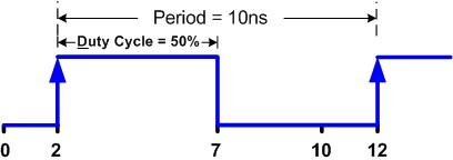
6.3.2.1 Example 1
create_clock -period 10 -waveform {2 7}
This example creates a clock with 10ns period, 2ns offset, and 50% duty cycle using the SDC command.
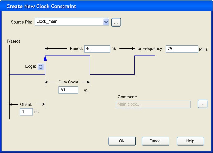
6.3.2.2 Example 2
This example shows how to create a clock with 25MHz frequency, 4ns offset for its first
rising edge, and 60% duty cycle using the SmartTime Constraints Editor. Using the Create
New Clock Constraint dialog box is equivalent to using the SDC command:
create_clock -period 40 -waveform {4, 28}.
6.3.3 Region
A region is a user-defined area on a chip into which you can constrain the physical placement of one or more macros. You can also constrain macros containing multiple tiles for cores, RAMs, and I/Os. The floorplanning process usually requires you to create several regions and assign logic to them. Logic can include core logic, memory, and I/O modules. When you run the place-and-route tool, it places the logic into their assigned regions.
Some regions are user-defined and others are automatically created by the tools to meet routing requirements (for example, Local clock regions).
You can use region constraints to:
- Create user-defined regions such as Inclusive, Exclusive, Empty, LocalClock, and QuadrantClock
- Assign and unassign macros to user-defined regions
- Constrain all the macros connected to a net by assigning them to a specific net region
- Move regions from one set of co-ordinates to another
6.3.4 Location
Each core, RAM, and I/O macro in the design is associated with a location on the device. When you run the place-and-route tool, it places all of your logic into their assigned locations.
You can use location constraints to:
- Overwrite the existing placements of macros
- Tell the place-and-route tool where to initially place the macros
- Assign I/O macros to specific pins to meet your board's requirements
6.3.5 I/O Attributes
I/O attributes are the characteristics of logic macros or nets in your design. They indicate placement, implementation, naming, directionality, and other characteristics. This information is used by the design implementation software during the place-and-route of a design.
Input and output attributes are described in the documentation for the I/O Attribute Editor. Attributes applicable to a specific tool are described in the documentation for that tool.
See the topics in I/O Attributes for more detailed information about each attribute.
6.3.5.1 About the I/O Attribute Editor
The I/O Attribute editor is available from the Libero IDE Project Manager, in the SmartDesign Microcontroller Subsystem configurator, and from MultiView Navigator.
6.3.5.1.1 I/O Attribute Editor Features
The I/O Attribute Editor is a graphical editor that enables you to:
- Create a new physical design I/O constraint
- Modify existing physical I/O constraints
- Import PDC I/O constraint files
- Automatically extract the ports at the top level of an HDL file
- Add, modify, or delete physical I/O constraints from SmartDesign
6.3.5.1.2 I/O Attribute Editor Advantages
- You can create and edit I/O constraints before compiling your design.
- It's efficient. You can re-use the same PDC file for two different modules.
- One module can use several different PDC files.
- You can add, modify, or delete a port from within the SmartDesign Canvas or Grid, and it is automatically updated in the I/O Attribute Editor. The PDC file is automatically passed from SmartDesign to Designer.
In Project Manager, you can edit constraints even before you have written any HDL code. You can edit I/O constraints using any text editor, as you did in previous versions, or you can use the graphical I/O Attribute Editor. You can create a new constraint file from the I/O Attribute Editor in Project Manager if you have a project open.
In Multiview Navigator, you can edit constraints only from a compiled netlist.
You cannot use all design constraints with all families; they are family and die specific.
6.3.5.1.3 Supported families
IGLOO, ProASIC3, SmartFusion, Fusion, Axcelerator, and RTAX-S
6.3.6 I/O Attribute Editor in Libero IDE Project Manager
The I/O Attribute Editor from MultiView Navigator is now integrated in the Libero IDE Project Manager and in SmartDesign. SmartDesign automatically passes I/O constraints to Designer.
You can define physical I/O constraints using I/O Attribute Editor from within the Project Manager.
You can start I/O Attribute Editor either from SmartDesign or by opening a PDC file from the Design Explorer.
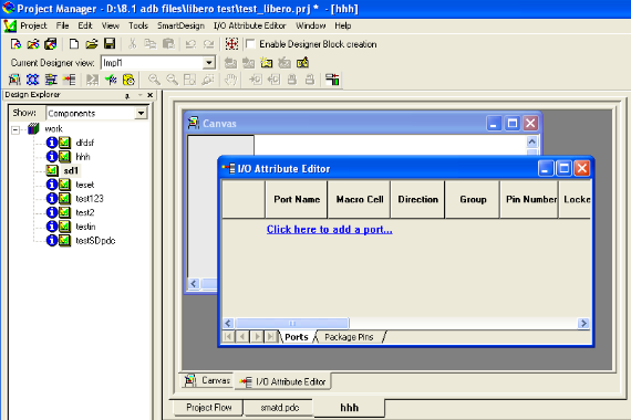
To start the I/O Attribute Editor from SmartDesign, from the SmartDesign menu, choose Show I/O Attribute Editor View. The I/O Attribute Editor opens in front of the SmartDesign Canvas as shown below.
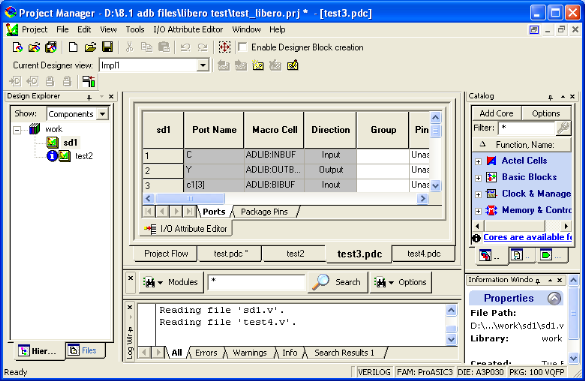
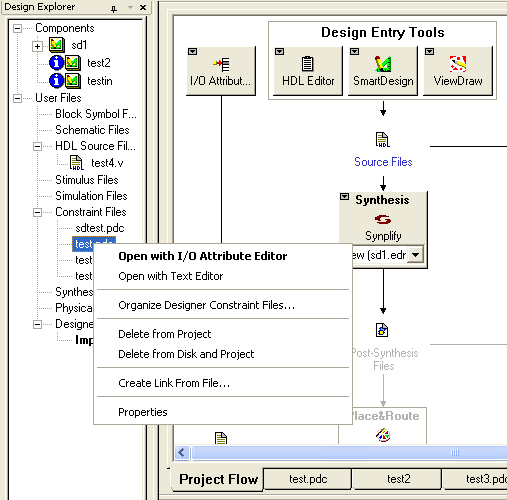
To open a PDC file from Design Explorer, right-click the file you want to open in the Files tab, and choose Open with I/O Attribute Editor as shown below.
You can either load an existing PDC into the I/O Attribute Editor, or you can create a new PDC file using the I/O Attribute Editor. When you load an existing PDC file, only the I/O-related constraints are shown in the I/O Attribute Editor. The other constraints are preserved and inserted at the end of the new, saved file.
6.3.7 I/O Attribute Editor Project Flow
I/O Attribute Editor enables you to view, create, and modify your physical design constraint (PDC) files. The Files tab lists your constraint files in alphabetical order.
- Step One - Create a new PDC file.
- Step Two - Add ports to your design.
- Step Three - Modify the I/O attributes.
- Step Four - Save the PDC file.
You can save your constraint file at any time.
6.3.7.1 Creating a New PDC File
You can create a new constraint file from the I/O Attribute Editor in Project Manager if you have a project open and a module set as root.
- From the File menu, choose New, or click the I/O Attribute Editor icon in
the Project Flow window. The New dialog box appears.
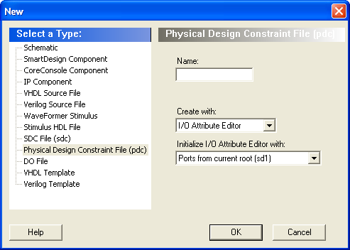
- Select Physical Design Constraint File (pdc) for the file type
- Type a name for the PDC file.
- In the Create with drop-down list, choose I/O Attribute Editor.
- In the Initialize I/O Attribute Editor with drop-down list, choose Ports from current root (sd1), or choose No Ports if you do not want to load the ports from the current root.
- Click OK. The I/O Attribute Editor opens, displaying the attributes of the PDC file you just created.
- From the File menu, choose Save <filename>.pdc. The saved file is added to your Libero IDE project.
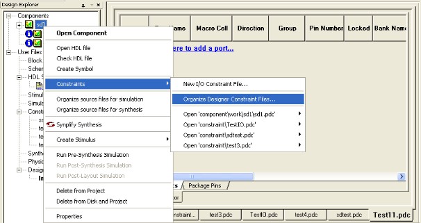
You can also use the right-click menu to create a new PDC file. Select and right-click the root module. Then choose Constraints > New I/O Constraint File from the right-click menu.
Suppose you just want to enter a constraint for a clock and reset the ports. In this case, you do not have to load all the ports before creating the new PDC file.
To create a new PDC file with the I/O Attribute Editor without loading all ports:
- From the File menu, choose New, or click the I/O Attribute Editor icon in the Project Flow window. The New dialog box appears.
- Select Physical Design Constraint File (pdc) for the file type.
- Type a name for the PDC file.
- In the Create with drop-down list, choose I/O Attribute Editor.
- In the Initialize I/O Attribute Editor with drop-down list, choose No Ports if you do not want to load the ports.
- Click OK. The I/O Attribute Editor opens, displaying the attributes of the PDC file you just created.
- Save the PDC file.
- Open the new PDC file in a text editor to confirm that only two constraints were exported for clock and reset.
- Right -click the root module, and choose
Constraints>Organize Designer Constraint Files to add the PDC file to Designer
as shown below.
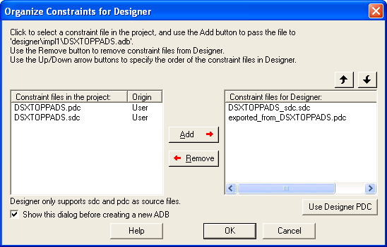
- In the Organize Constraints for Designer dialog box, select the files to pass to Designer, and click Add.
- Reopen the PDC file with the I/O Attribute Editor.
When you load ports from a module, the PDC file is automatically associated with that module. However, if no ports are loaded, you need to associate the PDC file using the Organize Designer Constraint Files command.
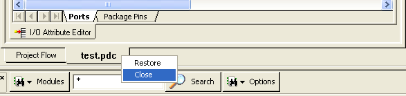
6.3.7.2 Opening an Existing PDC File
You can open an existing PDC file after you have opened a project and selected a module that contains the PDC file.
To open an existing PDC file do one of the following:
- In the Design Explorer, from the Files tab, expand the Constraint Files list, and double-click the PDC file you want to open. The main window displays the I/O Attribute Editor with the contents of the PDC fle.
- In the Design Explorer, click the Hierarchy tab, right-click the PDC file you want to open, and choose Constraints> Open <pdc filename>.
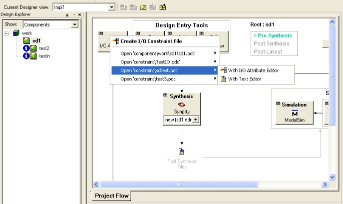
- Right-click the I/O Attribute Editor icon in the main window, choose the PDC file to open, and then choose whether to open it with the I/O Attribute Editor or with a text editor, as shown in the figure below.
The I/O Attribute Editor opens with the I/O attributes of the selected file. When you open an existing PDC file, only the I/O-related constraints are displayed in the I/O Attribute Editor.
6.3.7.3 Importing I/O Assignments
You can import I/O attributes from an existing PDC file into the I/O Attribute Editor. Constraints in the PDC file that are not I/O constraints are not read nor are they saved when you save the PDC file.
To import a PDC file into the I/O Attribute Editor of your design:
- From the I/O Attribute Editor menu, choose Import I/O Assignments. The Open dialog box appears.
- In the Open dialog box, find and select the PDC file to import, and click Open.
6.3.7.4 Use Designer PDC Constraints
You can enter pin constraints from Libero Project Manager by either using the text editor to add them to a PDC file or by using the I/O Attribute Editor.
Once you have imported I/O constraint files into Designer, you can modify the constraints with the MultiView Navigator. After modifying the constraints, you can import them back into Project Manager to use the most updated PDC file when performing an iterative design process.
When you use the Use Designer PDC feature, Libero Project Manager will do the following:
- Open the ADB file.
- Export all physical constraints.
- In Libero IDE, from the File menu, choose Import Files, and select the PDC file to import into the Libero project.
- Update the list of constraint files to be imported to Designer. The next time you start Designer, it will include this new PDC file instead of the other PDC files in the Libero project.
After selecting the Use Designer PDC feature, you can make more modifications to the newly added PDC file in Libero Project Manager.
To use the Use Designer PDC feature:
- Right-click an ADB file, and choose Use Designer PDC from the right-click menu.
- Right-click a Designer tool, and choose Use Designer PDC from the right-click menu.
- From the Organize Constraint Files for Designer dialog box, click Use Designer PDC. (The Use Designer PDC button does not appear until Layout is complete in Designer.)
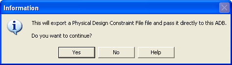
An Information box appears asking you to confirm that you want to export the Designer PDC file.
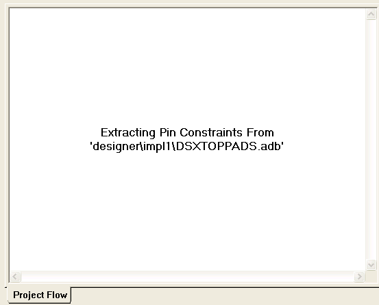
After you click Y es, a dialog box appears in which you enter a file name for this Designer PDC file. The default file name appears in the dialog. Click Save to replace the old PDC file with the newly modified one, or enter a new, unique name for the PDC which will be used for further design iterations. While converting the PDC file, a message appears,as shown below.
After selecting the Use Designer PDC feature, the Organize Constraints for Designer dialog box will organize the PDC file as the constraint file to be used by Designer the next time you start it up.
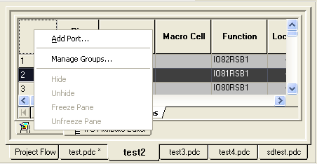
6.3.7.5 Adding, Modifying, and Deleting Ports
You can add ports to, delete ports from, and modify ports in the I/O Attribute Editor.
To add ports:
- From the I/O Attribute Editor
menu, choose Add port. The Add New Port dialog box appears (as
shown below).
Figure 6-7. Add New Port Dialog Box 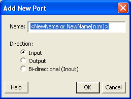
- Specify the name of the port you wish to add. You can specify a bus port by including the bus width as part of the name using brackets [ ], such as mybus[3:0].
- Select the direction of the port.
You can also add a port using the right-click menu.
To modify a port in the I/O Attribute Editor:
- Select the port in the Grid,
right-click and choose Modify Port. The Modify Port dialog box appears, as
shown in the figure below.
Figure 6-9. Modify Port Dialog Box 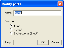
- Enter the new name for the port, change its direction, and click OK.
To remove a port from the I/O Attribute Editor, select the port in the Grid, right-click and choose Delete Port. Note: If you opened a PDC file associated with a module and the ports are loaded from the module, you cannot add, modify, nor delete the ports because they are brought over from the module.
6.3.7.6 Saving/Closing a PDC File
To save the current PDC file, from the File menu, choose Save <PDC filename>.pdc. The saved file is added to your Libero IDE project. The new constraints will override any existing constraints in this file. Any comments you added are not saved with this file. Therefore, you may want to save your changes into another file using the Save As menu command.
To save the current PDC file with a different name, choose Save <PDC filename>.pdc As. The Save As dialog box appears. Enter a new name for the PDC file.
6.3.7.7 Deleting a PDC File from a Libero IDE Project
To delete a PDC file from a project:
- In the Design Explorer, click the Files tab.
- Select the PDC file that you want to delete. Right-click the file name and select Delete from Project or Delete from Disk and Project, or click the Delete key to delete it from the project.
6.3.8 Assigning pins in Package Pins View
I/O Attribute Editor (v6.2 and higher) includes a Package Pins view in addition to its Ports view. Click the Package Pins tab to display your I/O attributes by package pin number. This view makes it much easier to assign address/data ports to adjacent pins. Additionally, it enables you to assign VREF pins (which you cannot do in Ports view) and to sort on banks.
6.3.8.1 Package Pins View
- Function
- Iis the functionality of the I/O (for example, GND or ground). See the datasheet for your device for details about each function.
- Dedicated
- Determines whether the pin is reserved for some special functionality, such as UJTAG / Analog Block / XTL pads inputs.
- VREF
- If checked, assigns the selected pin as a VREF (Voltage Referenced). This column only appears for devices that support VREF (IGLOOe, Fusion, ProASIC3L A3PE3000L, ProASIC3E, and Axcelerator). A device supports VREF if one or more of its I/O banks support VREF. IGLOO (excluding IGLOOe) and ProASIC3 (excluding ProASIC3L A3PE3000L and ProASIC3E) devices are not supported.
- User Reserved
- If checked, reserves the pin for use in another design. When a pin is reserved, you cannot assign it to a port. To unreserve the pin, deselect the User Reserved check box.
6.3.9 Editing I/O Attributes
You edit I/O attributes using the I/O Attribute Editor. It displays all assigned and unassigned I/O macros and their attributes in tabular format.
Use the I/O Attribute Editor to view, sort, select, and edit common and device-specific I/O attributes.
You can view the I/O attributes by port or by package pin. Click the Ports tab to view I/O attributes by port name. Click the Package Pins tab to view I/O attributes by pin number.
Each row corresponds to an I/O macro (port) or a pin in the design, depending on the view displayed. The column headings specify the names of the I/O attributes in your design. The first four column headings are standard for all families so they will not change. However, the other column headings will change depending on the family you are designing for. For some I/O attributes, you will choose from a drop-down menu; for others, you might enter a value.
To edit I/O attributes:
- Select an I/O standard for each I/O macro in your device.
- Select I/O attributes that are available for your selected I/O standard.
For descriptions of individual I/O attributes and support by family, refer to the I/O Attributes Reference section of the Design Constraints Guide.
6.3.10 Editing Multiple Rows
To edit multiple rows:
- Select the rows to edit. To select consecutive rows, click the first row, press and hold down the SHIFT key, and then click the last row. To select rows that are not consecutive, press and hold down the CTRL key, and then click each row to select. Continue to hold down the SHIFT or CTRL key.
- While still holding down the SHIFT or CTRL key, click in the cell containing the value you want to change. Release the SHIFT or CTRL key, and then release the mouse button.
The change occurs in all selected rows.
You can also select an entire column, which enables you to edit all rows in that column.
6.3.11 Sorting Attributes
You can sort rows by column in either ascending or descending order.
To sort I/O macros by attributes:
- Double-click a column heading to sort the table rows in ascending order.
- Double-click the column again to sort the table rows in descending order.
When sorted, an arrowhead appears in the column header to indicate the sort order.
6.3.12 Formatting Rows and Columns
When viewing and editing your input/output attributes, you can format the table to display only the attributes you want to see. Clicking the top-left cell selects all rows in the I/O Attribute Editor.
To hide one or more rows or columns:
- Select the row(s) or column(s) you want to hide from view.
- From the I/O Attribute Editor> Format menu, choose Row > Hide or Column > Hide, or right-click the row or column header and choose Hide from the right-click menu.
To show a hidden row or column:
- Select a range of rows or columns that span one or more hidden rows or columns.
- From the I/O Attribute Editor>Format menu, choose Row > Unhide or Column > Unhide, or right-click the row or column header and choose Unhide from the right-click menu.
Unhide also works for a selected column that has a hidden column to its immediate left or right (or both).
You can “freeze” (or lock) one or more columns so they remain visible on the screen as you scroll horizontally.
To freeze or lock one or more columns:
- Select the column to the right of the last column to freeze.
- From the I/O Attribute Editor>Format menu, choose Column > Freeze Pane, or right-click the column and choose Freeze Pane from the right-click menu.
To unfreeze one or more frozen columns, from the I/O Attribute Editor>Format menu, choose Column > Unfreeze Pane, or right-click any column header and choose Unfreeze Pane from the right-click menu. All frozen columns are unfrozen.
You can also resize all the columns and rows at once so their entire contents are visible.
You must unfreeze the current locked group before you can freeze another group.
To display a column's entire contents within it:
- Select the column(s) you want to display.
- From the I/O Attribute Editor>Format menu, choose Column >AutoFit. The width of the column either expands or contracts to fit only the cell heading and cell contents.
6.3.13 Manually Assigning Technologies to I/O Banks
The procedure for manually assigning technologies to I/O banks differs depending on whether you are designing for IGLOO, Fusion, ProASIC3, or Axcelerator devices.
To assign technologies to I/O banks in IGLOOe, Fusion, ProASIC3L, ProASIC3E, and Axcelerator devices:
- Select an I/O bank in either ChipPlanner or PinEditor.
- From the Edit menu, choose I/O Bank Settings.
- In the I/O Bank Settings dialog box,
select the technologies, and click Apply.
Selecting a standard selects all compatible standards and grays out incompatible ones. For example, selecting LVTTL also selects PCI, PCIX, and LVPECL, since they all have the same VCCI. Further, selecting GTLP (3.3 V) disables SSTL3 as an option because the VREFs of the two are not the same. Once you click Apply, the I/O bank is assigned the selected standards. Any I/O of the selected types can now be assigned to that I/O bank. Any previously assigned I/Os in the bank that are no longer compatible with the standards applied are unassigned.
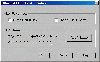
- Click More Attributes to set the low-power mode and input delay. (These attributes are supported in Axcelerator devices only.)
- Assign I/O standards to other banks by selecting the banks from the list and assigning standards. Any banks not assigned I/O standards use the default standard selected in the Device Selection Wizard.
- Leave the Use default pins for VREFs
option selected to set default VREF pins and unset non-default VREF pins. If you
unselect this option when setting a new VREF technology, no VREF pins are set. If you
unselect this option when default VREF pins are already set, it unsets them.
If the Use default pins for VREFs option is selected when you click OK or Apply, the software: 1) determines if setting default VREF pins causes any I/O macros to become unassigned, and if so, displays a warning message enabling you to cancel this operation, 2) determines if unsetting non-default VREF pins causes any I/O macros to become unassigned, and if so, displays a warning message enabling you to cancel this operation, and 3) sets default VREF pins and unsets non-default VREF pins.
- Click OK. Using PinEditor, proceed to
assign I/Os with the same standards to the appropriate banks.
Figure 6-11. I/O Bank Settings Dialog Box for IGLOOe, Fusion, ProASIC3L, ProASIC3E, and Axcelerator Devices 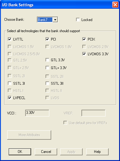
If VREF pins can be assigned, you must assign at least one VREF pin before running Layout. See "Assigning VREF Pins" in this guide for more information.
If you use I/O standards that need reference voltage, make sure to assign VREF pins. Microchip strongly recommends you use the defaults. VREF pins appear in red in ChipPlanner and are labeled VREF in PinEditor.
To set the low-power mode and input delay (for Axcelerator devices only):
- Click More Attributes in the I/O Bank Settings dialog box.
- Drag the slider bar to the desired delay. The delay is bank specific.
- Click View All Delays to see all the delay values (Best, Worst, Typical, Rise-Rise, Fall-Fall) for the input delay selected. You must select a technology to see the input delays.
- Click OK.
To assign technologies to I/O banks in ProASIC3 and IGLOO devices:
- Select an I/O bank in either ChipPlanner or PinEditor.
- From the Edit menu, choose I/O Bank Settings.
- In the I/O Bank Settings dialog box,
select the technologies, and click Apply.
Selecting a standard selects all compatible standards and grays out incompatible ones. For example, selecting LVTTL also selects PCI, PCIX, and LVPECL, since they all have the same VCCI. Note that LVDS is available only for banks 1 and 3. Once you click Apply, the I/O bank is assigned the selected standards. Any I/O of the selected types can now be assigned to that I/O bank. Any previously assigned I/Os in the bank that are no longer compatible with the standards applied are unassigned.
- Assign I/O standards to other banks by selecting the banks from the list and assigning standards. Any banks not assigned I/O standards use the default standard selected in the Device Selection Wizard.
- Click OK. Using PinEditor, proceed to
assign I/Os with the same standards to the appropriate banks.
Figure 6-13. I/O Bank Settings Dialog Box for IGLOO and ProASIC3 Devices 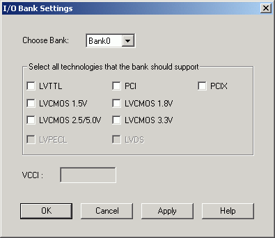
You cannot assign VREF pins in ProASIC3 and IGLOO devices. You can assign VREF pins only to IGLOOe, Fusion, ProASIC3L (A3PE3000L die only), and ProASIC3E devices.
6.3.14 Automatically Assigning Technologies to I/O Banks
The I/O Bank Assigner (IOBA) tool runs automatically when you run Layout. You can also use this tool from within the MultiView Navigator or from within Libero Project Manager. The I/O Bank Assigner tool automatically assign technologies and VREF pins (if required) to every I/O bank that does not currently have any technologies assigned to it. This tool is available when at least one I/O bank is unassigned.
Each time you run the I/O Bank Assigner, it unassigns all technologies from all I/O banks and then re-assigns them when it finds a feasible solution. To prevent I/O Bank Assigner from unassigning and re-assigning I/O technologies each time you run it, lock the I/O banks by selecting Locked in the I/O Bank Settings Dialog Box or by importing the
,set_iobanks PDC command with its -fixed argument set to "yes".
To automatically assign technologies to I/O banks:
- In Project Manager, from the I/O Attribute Editor menu, choose Tools>Auto-Assign I/O Banks.
- In MultiView Navigator, from the Tools menu, choose Auto-Assign I/O Banks. You can also click the I/O Bank Assigner's toolbar button shown below.
![]()
Messages appear in the Output window informing you when the automatic I/O bank assignment begins and ends. If the assignment is successful, "I/O Bank Assigner completed successfully" appears in the Output window.
If the assignment is not successful, an error message appears in the Output window. Click an underlined "Error" or "Info" message to display more information.
All I/O technologies assigned to I/O banks by the I/O Bank Assigner in Layout are unlocked.
To undo the I/O bank assignments, choose Undo from the Edit menu. Undo removes the I/O technologies assigned by the I/O Bank Assigner. It does not remove the I/O technologies previously assigned.
To redo the changes undone by the Undo command, choose Redo from the Edit menu.
If you need to clear I/O bank assignments made before using the Undo command, you can manually unassign or re-assign I/O technologies to banks. To do so, choose I/O Bank Settings from the Edit menu to display the I/O Bank Settings dialog box.
6.3.15 Reserving Pins for Device Migration
With this feature, you can begin a design with a larger device that you intend to implement later with a smaller device. Because there might be some pins on the smaller device that are not bonded, you want to make sure that the pin assignments created on the larger device are compatible with the pins on the smaller device. This feature reserves the pins on the larger device that are not bonded on the smaller device.
Pins in the current device that are not bonded in the target device will be marked as "reserved."
You can explicitly reserve a pin in PinEditor or I/O Attribute Editor (Package Pins view). You can also reserve a pin by importing a PDC constraint file with the reserve PDC command.
To explicitly reserve a pin in PinEditor:
- Select the pin to reserve, right-click it, and choose Reserve Pin from the right-click menu. (See screen below.) Repeat for each pin to reserve.
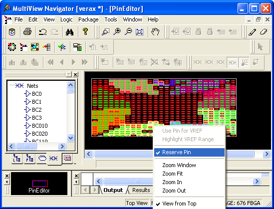
To unreserve a reserved pin from the right-click menu in PinEditor, select the pin to unreserve, right-click it, and choose Reserve Pin to remove the checkmark.
To explicitly reserve a pin in I/O Attribute Editor:
- In Package Pins view, select the User Reserved check box associated with the pin to reserve. (See screen below.) Repeat for each pin to reserve.
To automatically reserve pins that are not bonded in a destination device for migration, follow these steps:
- In PinEditor, from the Edit menu, choose Reserve Pins for Migration. The Reserve Pins for Migration dialog box appears. The current device for which the pins will be reserved appears in the Reserve pins in the current device text box.
- From the "that are not bonded in the target device" drop-down list, select the target device to which you will be migrating your design.
- Unselect the Keep explicitly-reserved pins check box if you do not want to save the pins that are currently explicitly reserved.
Choose Undo Reserve Package Pin from the Edit menu to unreserve the last pin you reserved.
To reserve pins with a PDC file:
- Open the PDC file to edit.
- Use the
reservecommand to specify the names of the pins to reserve.
To unreserve pins with a PDC file:
- Open the PDC file to edit.
- Use the
unreservecommand to specify the names of the pins to unreserve.SX-A devices do not support the reserved pins feature.
6.3.16 Specifying an I/O Standard
Use the I/O Standard column to select an I/O specification for each pin.
If required to match the I/O standard, other I/O attributes, such as I/O threshold, slew, and loading, are automatically set to their default settings; you cannot edit these defaults.
You can change the I/O standards only for a generic I/O buffer to any of the legal I/O standards.
To specify an I/O standard:
- Click the I/O Standard cell in the desired macro row.
- Type or select a supported I/O standard from the drop-down list.
For devices that support I/O banks (for example, Axcelerator devices), the list is restricted to legal choices only. When an I/O is assigned, the I/O standards available for that I/O are limited to what the I/O bank location can support.
Changing an I/O standard may also unassign existing I/Os. In addition, when a macro is assigned an I/O standard, the I/O bank is automatically assigned the voltages VCCI and VREF, if necessary. Unassigning this macro will undo these assignments as well.