
1.8.4.5 Opening VCD File in ModelSim
(Ask a Question)To view the signals exported by the SmartDebug in the
.vcd file, use the Modelsim Waveform window:
- Open ModelSim.
- Go to the Transcript window and convert
VCD to WLF format using the following the
vcd2wlf <file1.vcd>
               <file2.wlf>
command as shown in the following figure.Figure 1-30. VCD to WLF Conversion  Important: Conversion errors are most often caused by a nonexistent instance path. Ensure that the instance paths specified are correct.
 - Open the WLF file created using File menu Open -> file2.wlf.
- Select window with wlf file name and add
signals to the Waveform window, as shown in the following figure.
Figure 1-31. Adding Signals 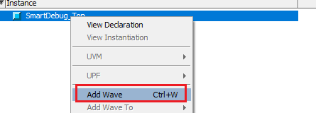
- Open the Wave window. Observe that the
error signal is not asserted indicating data written and date read from DPSRAM is same,
as shown in the following figure.
Figure 1-32. Wave Window 
Important: The Fabric_Debug block includes the match_out signal,
which must always be high, indicating that the data expected from DPSRAM and the data read
from DPSRAM matches. But the provided design has a bug due to which the match_out signal
always toggles. Debug the match_data.v logic using the FHB feature and find the route
cause. Add match_out and mem_out of count_chk_0 block to Active probe and export the
signals. Observe when the match_out signal is asserted to 1'b0.