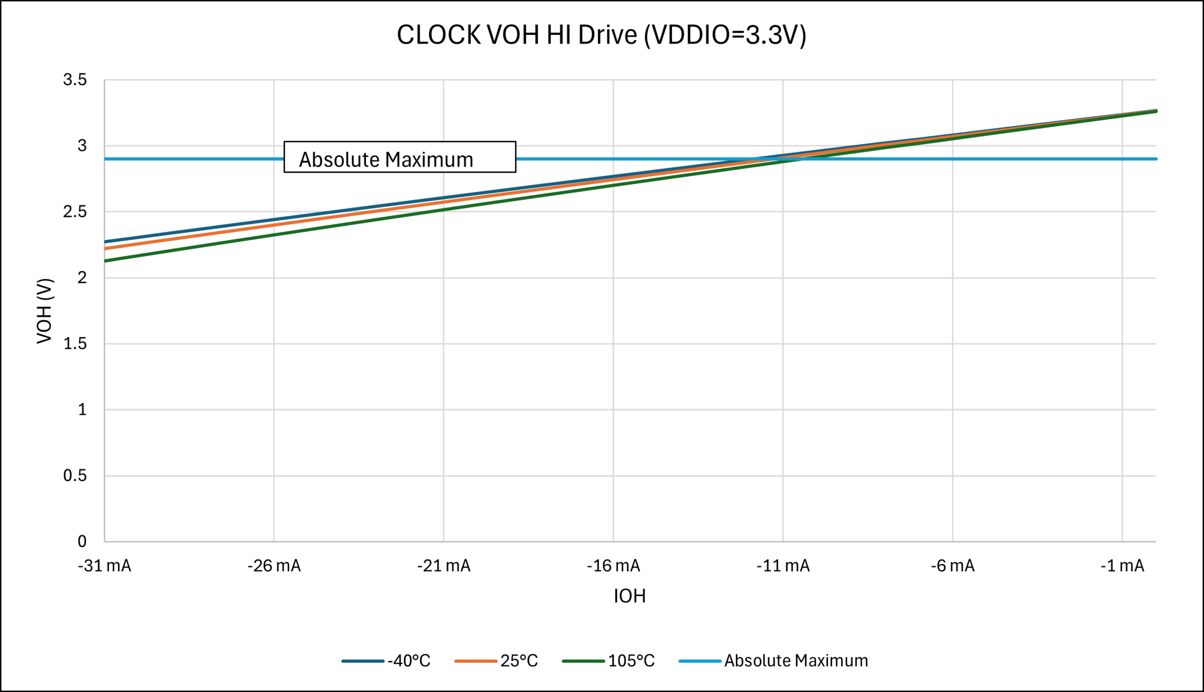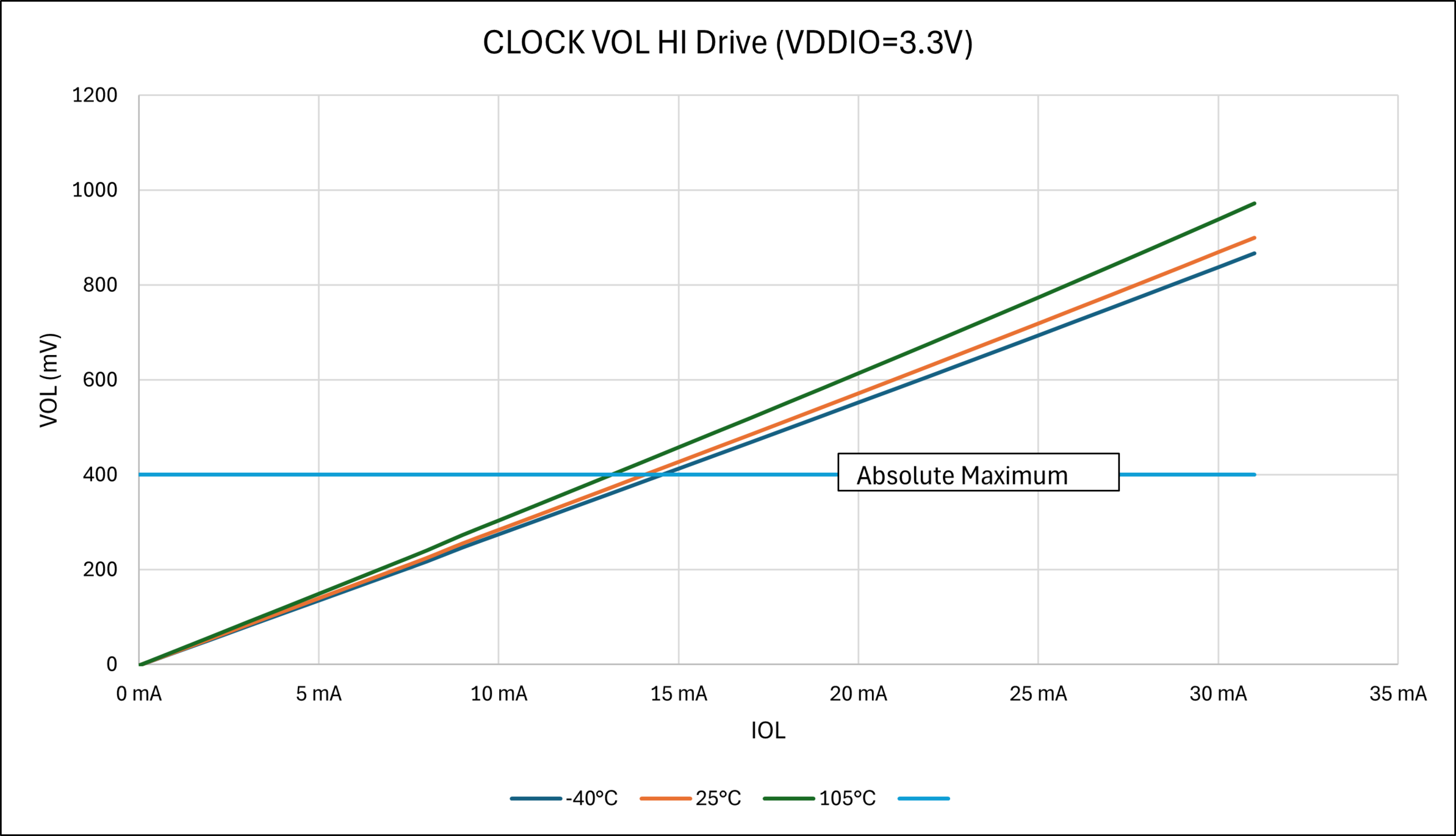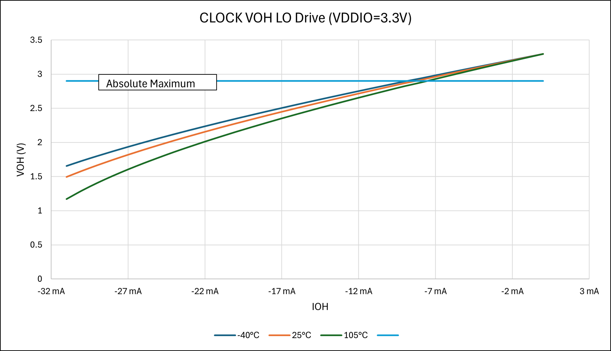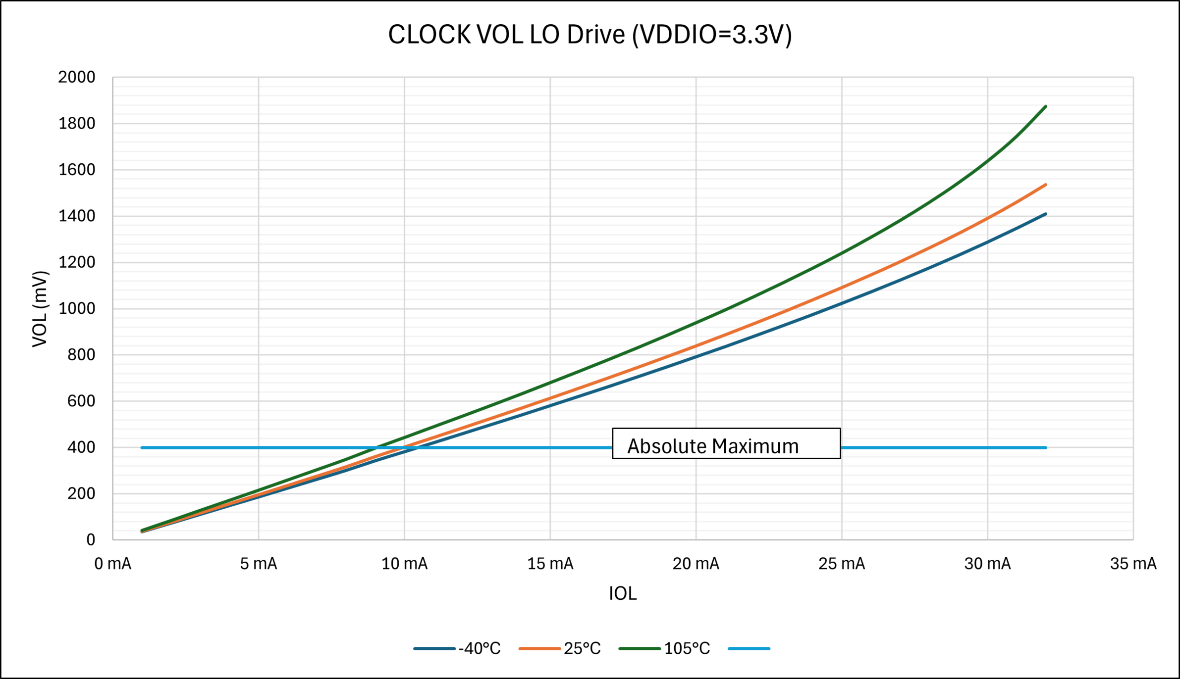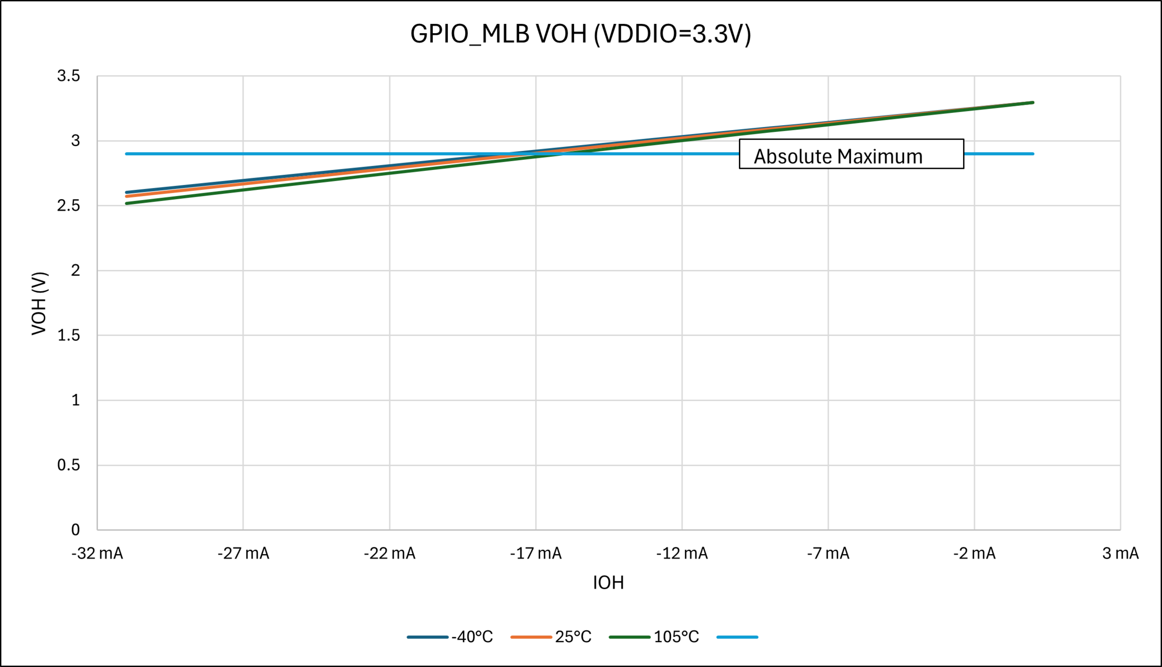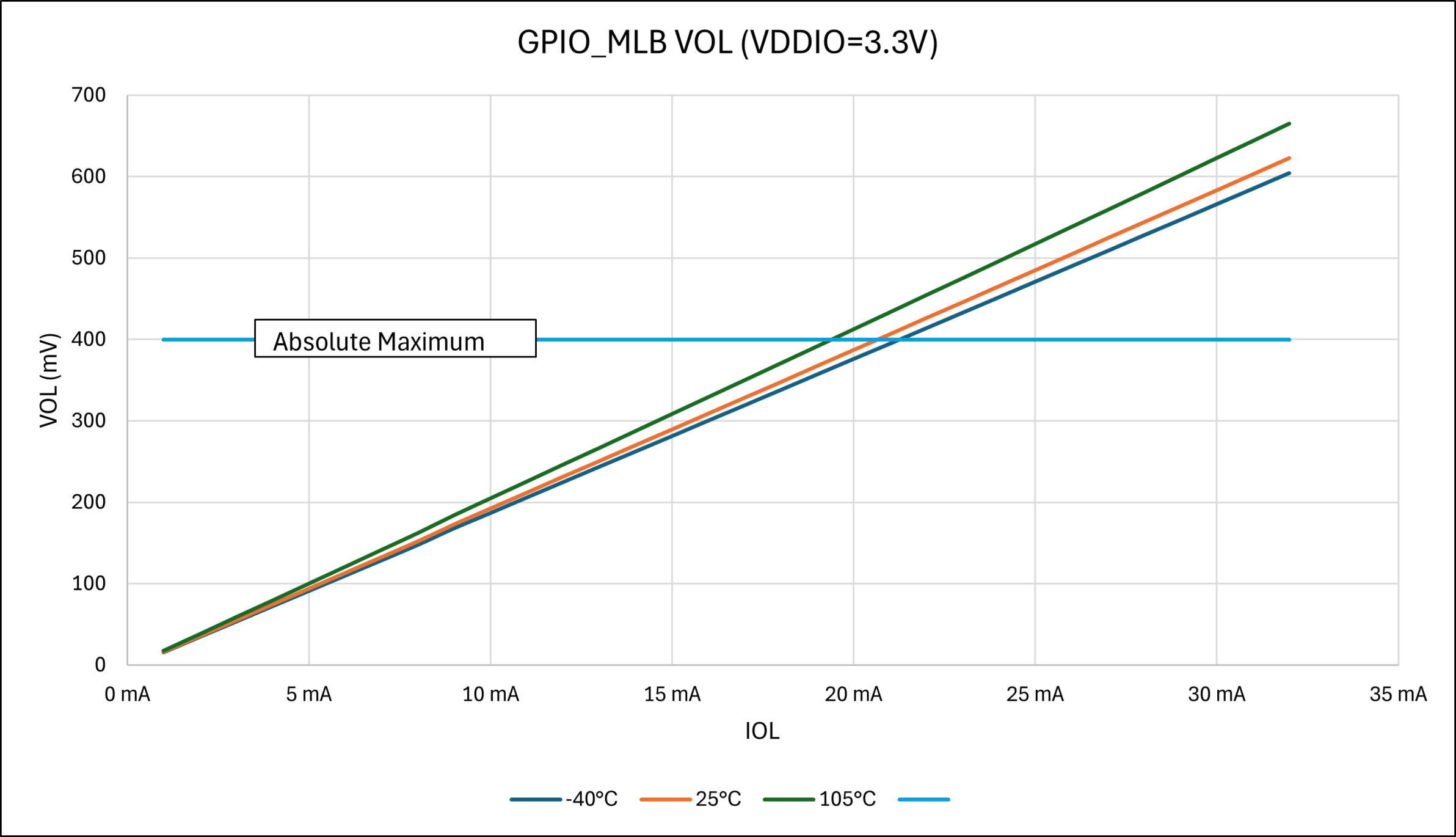
57.10 I/O Pin Electrical Specifications
| AC - DC CHARACTERISTICS | Standard
Operating Conditions: VDDIO = VDDIN 2.5V to 3.6V (unless otherwise
stated) Operating temperature: -40°C ≤ TA ≤ +85°C for Industrial | ||||||
|---|---|---|---|---|---|---|---|
| Param. No. | Symbol | Characteristics | Min. | Typ. | Max. | Units | Conditions |
| DI_1 | VIL | Input Low-Voltage GPIO, CLOCK, NRST, TST I/O Pins | -0.3 | — | 0.3 × VDDIO | V | — |
| Input Low-Voltage GPIO_AD, GPIO_CLK I/O Pins | -0.3 | — | 0.8 | V | — | ||
| Input Low-Voltage GPIO_MLB I/O Pins | -0.3 | — | 0.7 | V | — | ||
| DI_3 | VIH | Input High-Voltage GPIO, CLOCK, NRST, TST I/O Pins | 0.7 × VDDIO | — | VDDIO + 0.3 | V | — |
| Input High-Voltage GPIO_AD, GPIO_CLK I/O Pins | 2 | — | VDDIO + 0.3 | V | — | ||
| Input High-Voltage GPIO_MLB I/O Pins | 1.8 | — | VDDIO + 0.3 | V | VDDIO = VDDIN ≥ 2.7V (Media Local Bus function only) | ||
| DI_5 | VOL | GPIO, NRST, TEST, CLOCK I/O pins
Low Drive Strength (Output Low Voltage) | — | — | 0.4 | V | VDDIO = 3.3V @ IOL = -4 mA |
| GPIO, NRST, TEST, CLOCK I/O pins
High Drive Strength (Output Low Voltage) | — | — | 0.4 | V | VDDIO = 3.3V @ IOL = -10 mA | ||
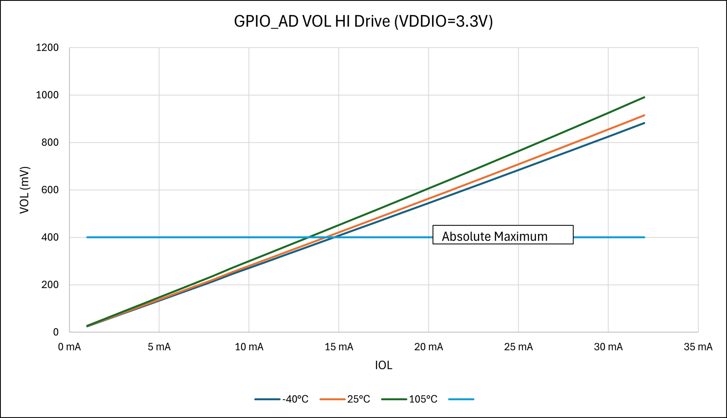
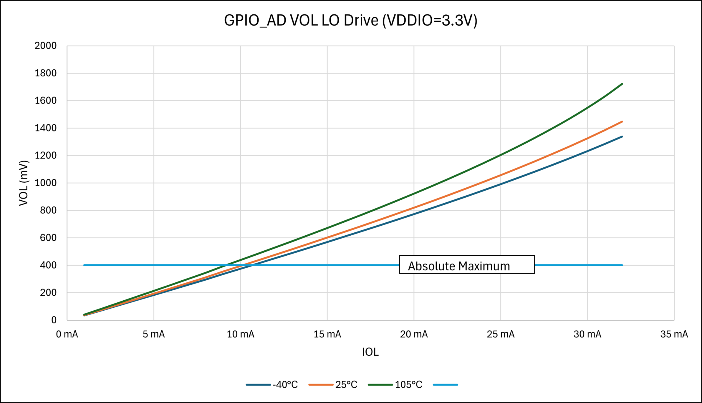
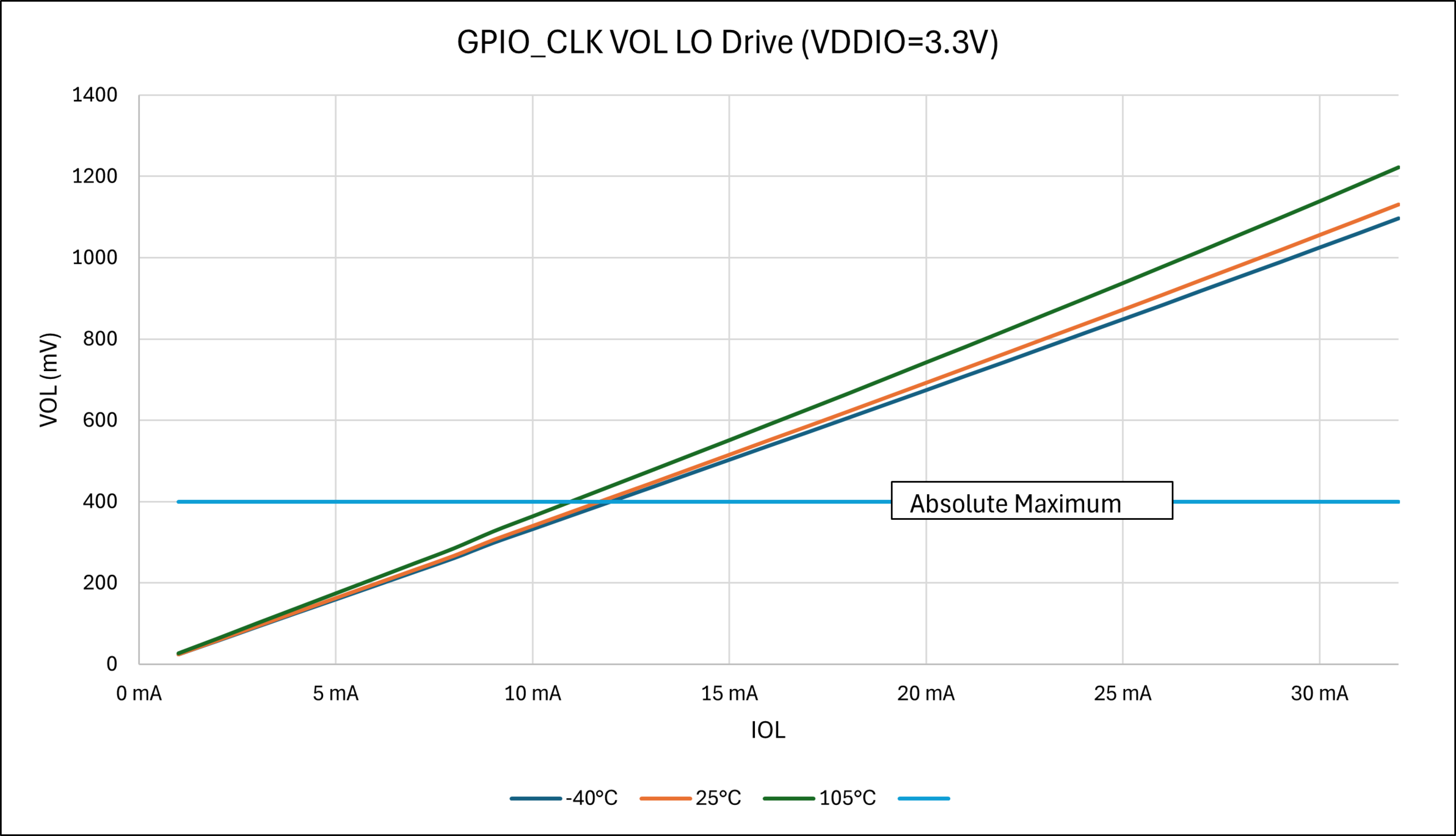
| GPIO_CLK, GPIO_AD I/O pins Low Drive Strength (Output Low Voltage) | — | — | 0.4 | V | VDDIO = 3.3V @ IOL = -6 mA | ||
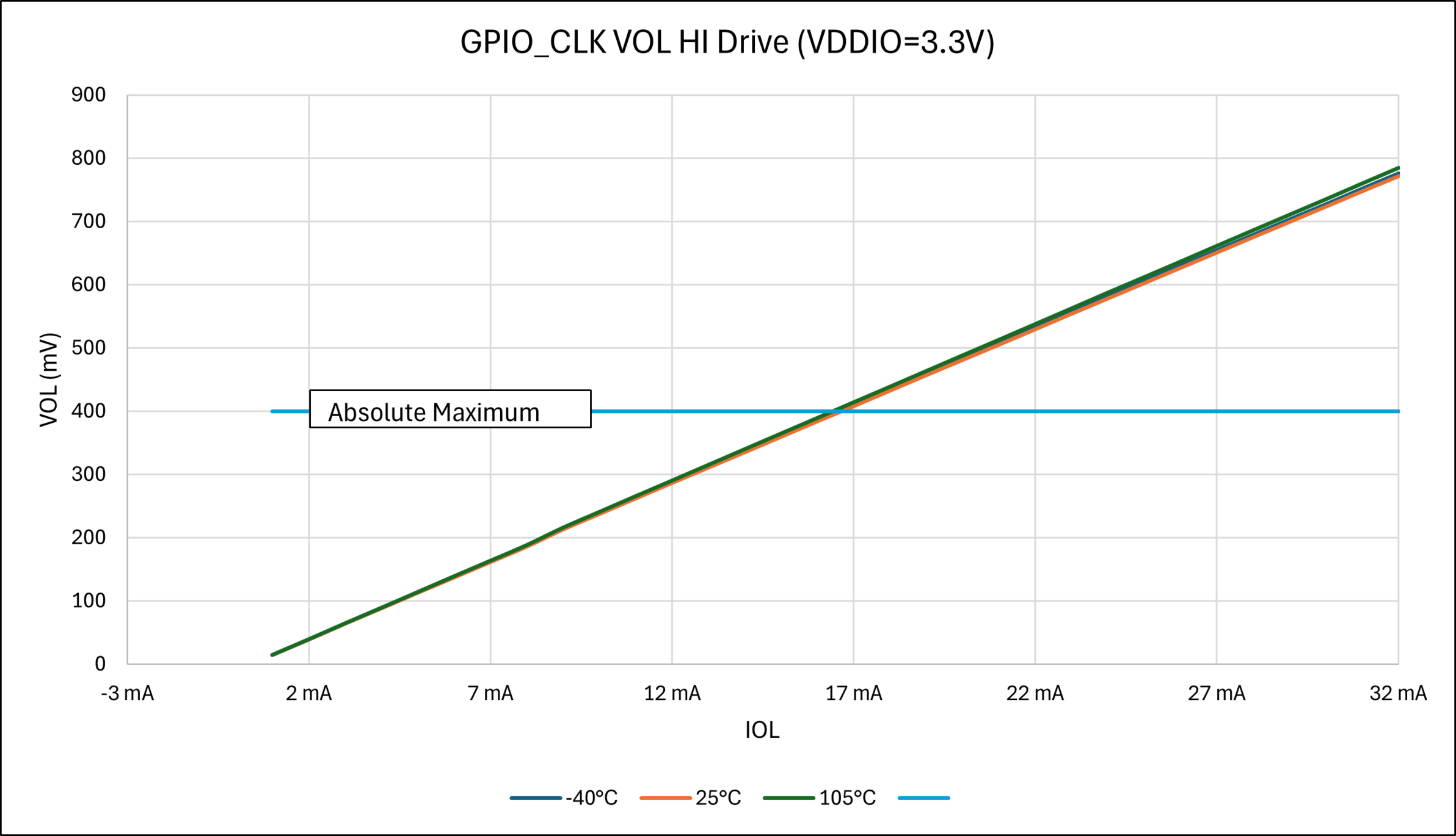
| GPIO_CLK, GPIO_AD I/O pins High Drive Strength (Output Low Voltage) | — | — | 0.4 | V | VDDIO = 3.3V @ IOL = -12 mA | ||
| GPIO_MLB I/O pins Drive Strength (Output Low Voltage) | — | — | 0.4 | V | VDDIO = 3.3V @ IOL = -6 mA | ||
| DI_9 | VOH | GPIO, NRST, TEST, CLOCK I/O pins
Low Drive Strength (Output High Voltage) | VDDIO - 0.4 | — | — | V | VDDIO = 3.3V @ IOH = 4 mA |
| GPIO, NRST, TEST, CLOCK I/O pins
High Drive Strength (Output High Voltage) | VDDIO - 0.4 | — | — | V | VDDIO = 3.3V @ IOH = 10 mA | ||
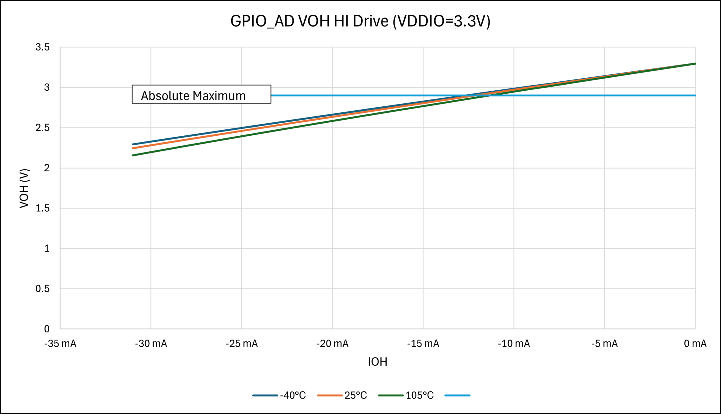
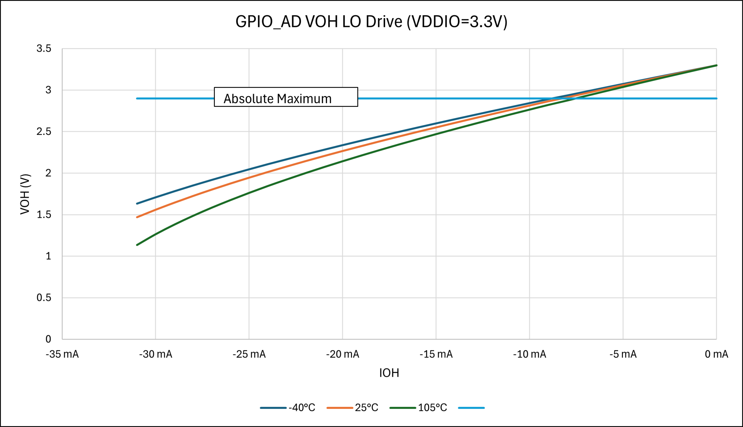
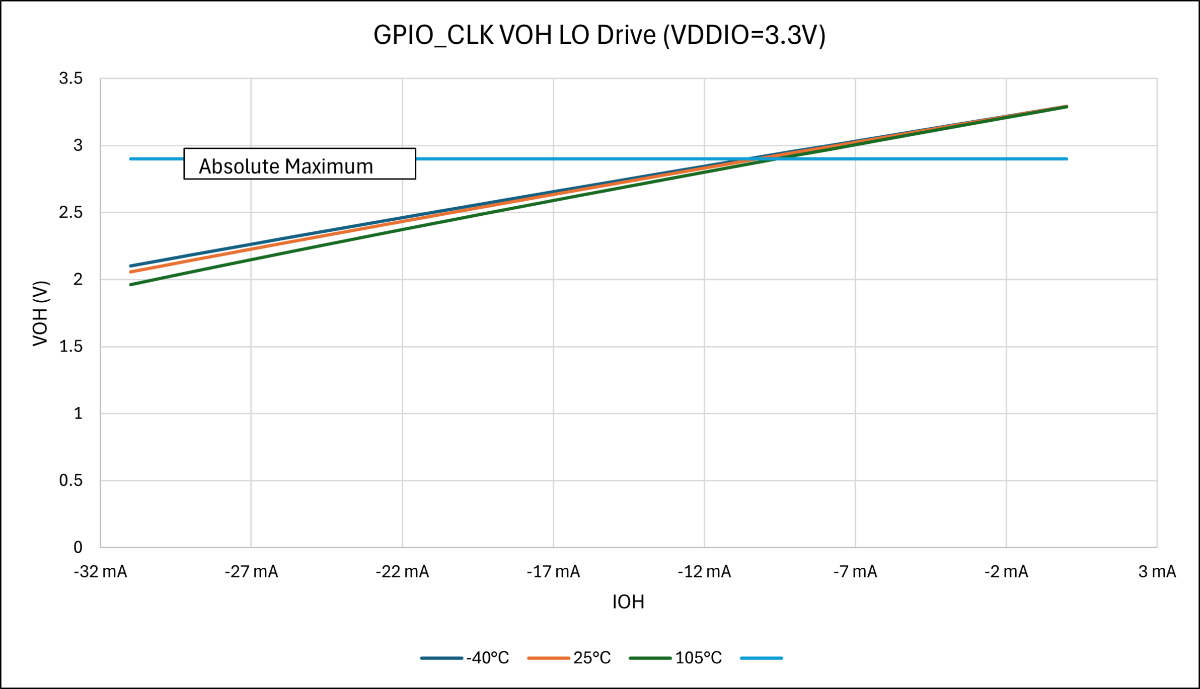
| GPIO_CLK, GPIO_AD I/O pins Low Drive Strength (Output High Voltage) | VDDIO - 0.4 | — | — | V | VDDIO = 3.3V @ IOH = 6 mA | ||
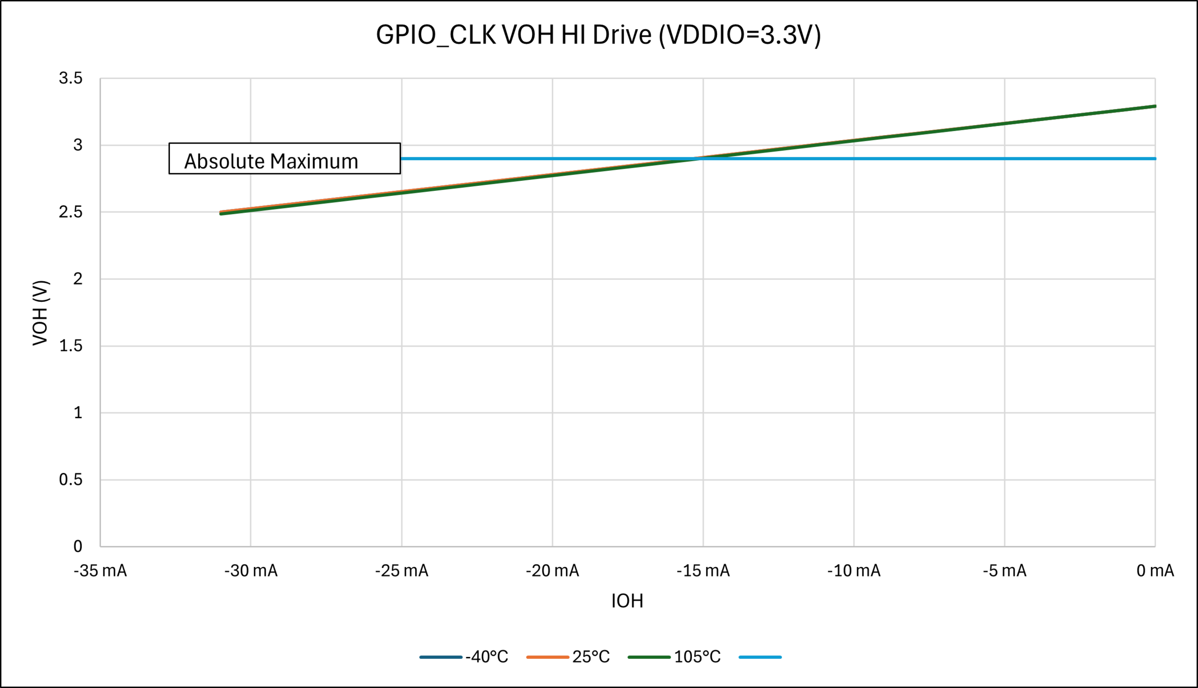
| GPIO_CLK, GPIO_AD I/O pins High Drive Strength (Output High Voltage) | VDDIO - 0.4 | — | — | V | VDDIO = 3.3V @ IOH = 12 mA | ||
| GPIO_MLB I/O pins Drive Strength (Output High Voltage) | 2 | — | — | V | VDDIO = 3.3V @ IOH = 6 mA | ||
| DI_11 | Rserial | GPIO, NRST, TEST, CLOCK I/O pins | — | 9.5 | — | Ω | — |
| GPIO_CLK, GPIO_AD I/O pins | — | 11.2 | — | — | |||
| GPIO_MLB I/O pins | — | 5.3 | — | — | |||
| DI_15a | RPDWN | Internal Pull-Down Enabled
(PIO_PPDER = 1) except JTAGSEL pin | 70 | 110 | 140 | kΩ | — |
| DI_15b | RPDWN | Internal Pull-Down JTAGSEL pin | — | 15 | — | kΩ | — |
| DI_17 | RPUP | Internal Pull-Up Enabled (PIO_PUER = 1) | 70 | 110 | 140 | kΩ | — |
| DI_19 | IICL | Input Low Injection Current | -15 | — | — | mA | This parameter applies to all I/O pins. |
| DI_21 | IICH | Input High Injection Current | — | — | 10 | mA | This parameter applies to all pins, with the exception of 5V tolerant I/O pins. |
| DI_23 | ∑IICT | Total Input Injection Current (sum of all I/O and control pins) Absolute value of | ∑IICT | | -45 | — | 60 | mA | Absolute instantaneous sum of all ±
input injection currents from all I/O pins. ( | IICL | + | IICH | ) ≤ ∑IICT |
| DI_25 | TRISE (1) | GPIO, NRST, TST, CLOCK I/O pins Rise
Time Low-Drive Strength (PIO_DRIVER = 0) | — | 3.6 | 6 | ns | CLOAD = 30 pF |
| GPIO_AD, GPIO, NRST, TST, CLOCK I/O
pins Rise Time High-Drive Strength (PIO_DRIVER = 1) | — | 1.8 | 4 | ns | |||
| GPIO_CLK, GPIO_AD I/O pins Rise Time
Low-Drive Strength (PIO_DRIVER = 0) | — | 3.4 | 6 | ns | |||
| GPIO_CLK, GPIO_AD I/O pins Rise Time
High-Drive Strength (PIO_DRIVER = 1) | — | 1.7 | 4 | ns | |||
| GPIO_MLB I/O pin Rise Time | — | 1.1 | 3 | ns | |||
| DI_27 | TFALL(1) | GPIO, NRST, TST, CLOCK I/O pins Fall
Time Low-Drive Strength (PIO_DRIVER = 0) | — | 2.9 | 6 | ns | |
| GPIO, NRST, TST, CLOCK I/O pins Fall
Time High-Drive Strength (PIO_DRIVER = 1) | — | 1.5 | 4 | ns | |||
| GPIO_CLK, GPIO_AD I/O pins Fall Time
Low-Drive Strength (PIO_DRIVER = 0) | — | 2.6 | 6 | ns | |||
| GPIO_CLK, GPIO_AD I/O pins Fall Time
High-Drive Strength (PIO_DRIVER = 1) | — | 1.4 | 4 | ns | |||
| GPIO_MLB I/O pin Fall Time | — | 1.0 | 3 | ns | |||
|
Note:
| |||||||