
57.22 USART Electrical Specifications
| AC CHARACTERISTICS | Standard
Operating Conditions: VDDIO = VDDIN 2.5V to 3.6V (unless otherwise
stated) Operating temperature: -40°C ≤ TA ≤ +85°C for Industrial | |||||||
|---|---|---|---|---|---|---|---|---|
| Param. No. | Symbol | Characteristics | Min. | Typ. | Max. | Units | Conditions | |
| UT_1 | FBRATE | Baud Rate | Asynchronous 16x over-sampling mode (US_MR.OVER = 0x0) | — | — | FCLK_3/16 | Mbps | VDDIO = 3.3V, CLOAD = 30 pF |
| UT_3 | Asynchronous 8x over-sampling mode (US_MR.OVER = 0x1) | — | — | FCLK_3/8 | Mbps | VDDIO = 3.3V, CLOAD = 30 pF | ||
| UT_19 | Synchronous Host Mode (Internal clock) | — | — | 25 | Mbps | VDDIO = 3.3V, CLOAD = 30 pF | ||
| UT_21 | Synchronous Client Mode (External clock) | — | — | 25 | Mbps | VDDIO = 3.3V, CLOAD = 30 pF | ||
| UT_25 | FXCK | USART External Clock | — | — | 25 | MHz | - | |
|
Note:
| ||||||||
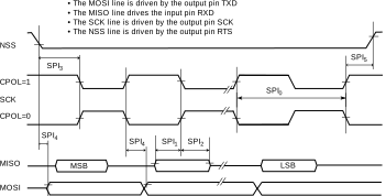
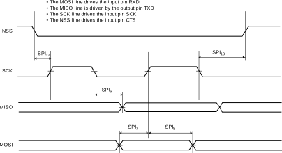
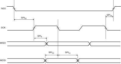
| AC CHARACTERISTICS | Standard
Operating Conditions: VDDIO = VDDIN 2.5V to 3.6V (unless otherwise
stated) Operating temperature: -40°C ≤ TA ≤ +85°C for Industrial | |||||||
|---|---|---|---|---|---|---|---|---|
| Param. No. | Symbol | Characteristics | Min. | Typ. | Max. | Units | Conditions | |
| Host Mode | ||||||||
| SPI_0 | THSCK | SCK Period | FLCK_3/6 | — | — | ns | VDDIO = 3.3V, CLOAD = 30 pF | |
| SPI_1 | THISU | Input Data Setup Time | 1.645 | — | — | ns | VDDIO = 3.3V, CLOAD = 30 pF | |
| SPI_2 | THIHU | Input Data Hold Time | 0.396 | — | — | ns | VDDIO = 3.3V, CLOAD = 30 pF | |
| SPI_3 | THSSS | Chip Select Active to Serial Clock | -0.795 | — | — | ns | VDDIO = 3.3V, CLOAD = 30 pF | |
| SPI_4 | THOSU | Output Data Setup Time | -0.926 | — | 8.985 | ns | VDDIO = 3.3V, CLOAD = 30 pF | |
| SPI_5 | THSSI | Serial Clock to Chip Select Inactive | -1.935 | — | 4.502 | ns | VDDIO = 3.3V, CLOAD = 30 pF | |
| Client Mode | ||||||||
| SPI_6 | TCSCKF | SCK falling to MISO | 3.694 | — | 13.098 | ns | VDDIO = 3.3V, CLOAD = 30 pF | |
| SPI_7 | TCSUR | MOSI Setup time before SCK rises | 1.311 | — | — | ns | VDDIO = 3.3V, CLOAD = 30 pF | |
| SPI_8 | TCHUR | MOSI Hold time after SCK rises | 0.497 | — | — | ns | VDDIO = 3.3V, CLOAD = 30 pF | |
| SPI_9 | TCSCMISO | SCK rising to MISO | 3.778 | — | 13.118 | ns | VDDIO = 3.3V, CLOAD = 30 pF | |
| SPI_10 | TCSUF | MOSI Setup time before SCK falls | 1.438 | — | — | ns | VDDIO = 3.3V, CLOAD = 30 pF | |
| SPI_11 | TCHUF | MOSI Hold time after SCK falls | 0.476 | — | — | ns | VDDIO = 3.3V, CLOAD = 30 pF | |
| SPI_12 | TCNSSR | NPCS0 Setup to SCK rising | 0.332 | — | — | ns | VDDIO = 3.3V, CLOAD = 30 pF | |
| SPI_13 | TCNSHF | NPCS0 Hold after SCK falling | 0.837 | — | — | ns | VDDIO = 3.3V, CLOAD = 30 pF | |
| SPI_14 | TCNSSF | NPCS0 Setup to SCK falling | 0.389 | — | — | ns | VDDIO = 3.3V, CLOAD = 30 pF | |
| SPI_15 | TCNSHR | NPCS0 Hold after SCK rising | 0.889 | — | — | ns | VDDIO = 3.3V, CLOAD = 30 pF | |
|
Note:
| ||||||||