9.22.3 Analog Block Configuration Dialog Box (Fusion Only)
Enables you to:
View the channel configuration on your analog system, identify if/how the channels are configured.
Compare with the design configuration from
the Analog System Builder
The values displayed for each channel vary depending on the channel you select; the dialog box
may display the following values:
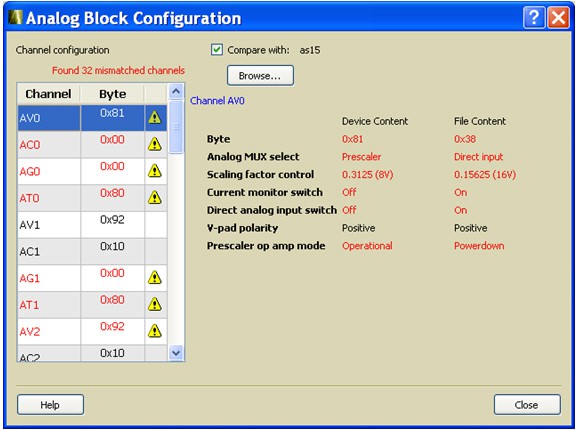
Byte - 8-bit raw byte data read from the
ACM of the respective analog. Individual, decoded bit fields of the byte are presented in
the following list:
Analog MUX select
Internal chip T monitor
Scaling factor control
Current monitor switch
Current monitor drive control
Direct analog input switch
Pad polarity - G, T, V, C pad
polarity, positive or negative
Select low/high drive
Prescaler op amp mode
To use the compare feature complete the following steps:
Select the Compare with checkbox.
Click Browse and navigate to the Analog System
Builder directory.
In a typical IDE project, this directory is located at
<project_root>/smartgen/<analog_block_core_name>.
After specifying the compare directory the differences (if any) are indicated in red on a channel
by channel basis, as shown in the following figure.Figure 9-147. Analog Block Configuration Dialog Box (Differences in Red)