1.8.7.5 Eye Monitor
(Ask a Question)Eye Monitor enables visualizing the eye diagram present within the receiver. This feature plots the receiving eye after the CTLE and Receiver functions. The diagram representation provides vertical and horizontal measurements of the eye measurement and BER performance measurements. Whenever PRBS/static pattern transmission is in progress, click the Eye Monitor tab in the Debug TRANSCEIVER window to see the eye monitor representation within the receiver.
In Libero SoC, the following types of Eye Scan modes are supported:
- Normal mode—In this mode, Eye Monitor performs a single eye scan and displays the Eye Diagram on the Eye Monitor plot.
- Infinite Persistent Mode—In this mode, the Plot Eye button changes to Start Plot Eye. Select Start Plot Eye to start infinite persistent eye monitoring. The Start Plot Eye button changes to Stop Plot Eye, and the infinite scanning and accumulation process begins. In every iteration, the eye is cumulated with all previous eyes to make a single cumulative eye. This cumulative eye is displayed with a color scheme on the Eye Monitor plot. The completed iteration number and the cumulative BER are updated and displayed after every iteration, along with the cumulative eye. To stop cumulative eye monitoring, click the Stop Plot Eye button. The process halts after the current iteration completes.
- Design Initiated Eye Plots—In this mode, the Select Eye Output drop-down is enabled when an Eye Plot log file is browsed and loaded on the Eye Monitor page. Click Browse File to load the Eye Plot output files. If the loaded Design Initiated Eye Plot log file does not contain any eye output, it is disabled. After selecting Eye output from the Select Eye Output drop-down, click Plot Eye to start eye monitoring for the lane. Then the Eye diagram displays the selected log file.
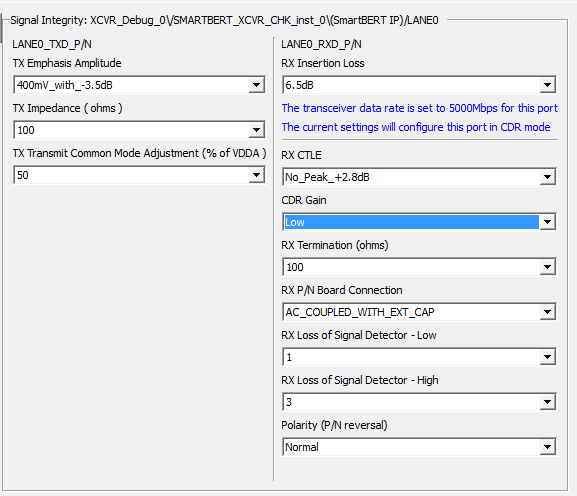
The following figure shows the recommended SI settings for the demo design. These settings are for the short reach and less lossy cables.
To plot the Eye Diagram, perform the following steps:
- Go to EYE Monitor tab and Select LANE0.
- Click Power on Eye Monitor.
- Go to SmartBERT tab, select LANE0 and choose any probes pattern and click Start.
- Go back to Eye
Monitor tab and click Plot Eye to plot the
eye.
The Eye Plot of the Signal in LANE0 is plotted.
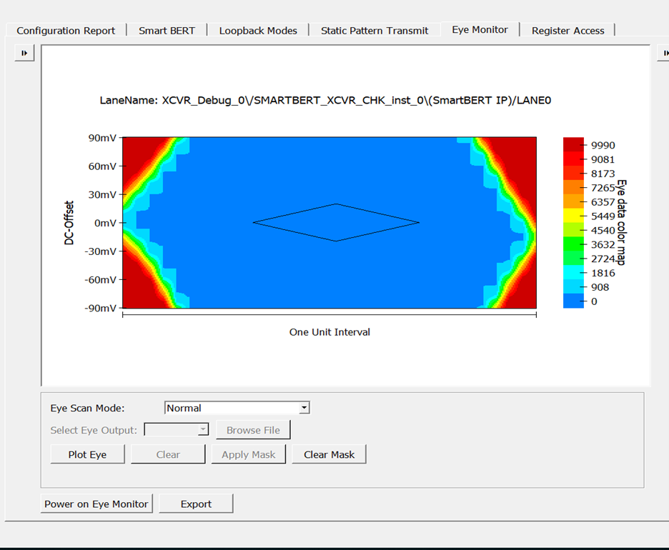
The following figure shows the Eye Monitor tab.
Figure 1-43. Debug TRANSCEIVER—Eye Monitor 
- After plotting the Eye diagram, the user can use the Apply Mask option to know the best eye-opening with the least errors. The Apply Mask and the Clear Mask options are disabled in the Default View. Click Plot Eye to enable the Apply Mask option.
- After selecting the Apply
Mask option, the Clear Mask option is enabled, and the Eye Mask for the
Eye Plot appears, as shown in the following figure.
Figure 1-44. Eye Monitor GUI After Applying the Mask Using Apply Mask Button