
2.1.3 Analog System Builder Main Window
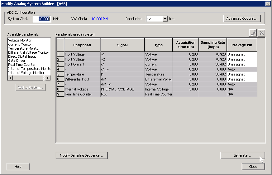
The Analog System Builder main window enables you to create and configure your analog system, as shown in the following figure.
The number of peripherals you can add to the system depends on the resources available on the selected device.
- ADC Clock and Resolution
-
The ADC clock is the frequency at which analog‑to‑digital conversions occur. The Analog System Builder (ASB) evaluates the required acquisition times for all peripherals and the system frequency to compute the maximum possible ADC clock frequency. Only certain divider factors are available to generate the ADC clock; therefore, depending on peripheral acquisition times, some system frequencies result in a higher ADC clock frequency than others. For more information, see the Designing with Analog System Builder section.
You can select the resolution of the analog‑to‑digital converter (ADC) in 8-bit, 10‑bit, or 12‑bit mode. The selected resolution determines which bits are meaningful in the ADCRESULT port, ASSC RAM, and SMEV RAM:
- 12‑bit mode: Bits [11:0] are used.
- 10‑bit mode: Bits [11:2] are used; bits [1:0] are grounded.
- 8‑bit mode: Bits [11:4] are used; bits [3:0] are grounded.
- Advanced Options
-
Click on Advanced Options to configure advanced analog system settings.
- Available Peripherals
-
The Available Peripherals list shows all analog peripherals that can be added to the design. As peripherals are added, device resources are consumed. If the resource limit is exceeded, ASB issues a warning during file generation. To add more peripherals, select a larger device or remove existing peripherals from the design.
- Peripherals Used in System Grid
-
The Peripherals Used in System grid displays information for each configured peripheral, including the following:
- Peripheral: The type of peripheral (for example, Voltage Monitor or Temperature Monitor).
- Signal: The name specified for the service signal in the service configuration dialog box.
- Type: The channel type for the service.
- Acquisition Time: The required acquisition time for the input channel. ASB uses the acquisition times of all peripherals to compute the maximum possible ADC clock frequency and the number of ADC clock cycles per sample and per peripheral.
- Sampling Rate (µs): The sampling rate for channels specified in the Main procedure. For more information, see Modify Sampling Sequence and Sampling rate in Analog System Builder.
- Package Pin: The package pin automatically assigned by ASB for each channel. If required, you can manually select a specific package pin to accommodate board‑layout constraints.
- Real Time Counter: You can configure the Real Time Counter (RTC) to operate as a chronometer and generate periodic alarms in conjunction with other peripherals, such as the Voltage Monitor.
- Modify Sampling Sequence
-
The Modify Sampling Sequence option displays the Sample Sequencer. Since there are 30 analog input channels but only one ADC, the channels need to be sequenced in the order they are sampled.
- Resources and Naming Warnings
-
If the analog system configuration exceeds the total resources available on the selected device, ASB issues a warning and stop system from being generated. ASB also warns if there is a port-name conflict between two or more services. Systems with resource violations or port-name conflicts cannot be generated.
- File Generation
-
When you click Generate ..., ASB creates HDL source files, memory (MEM) files, configuration files, and log files. These files are stored in the project folder under the
<core_name>directory. Do not modify these generated files or add other files to this directory. The directory is recreated each time the core is regenerated.