
2.1.24 Analog System Builder and Flash Memory Block Basic Configuration
The following figure illustrates the default configuration exported when using basic ASB features and an FMB configured with an analog client only.
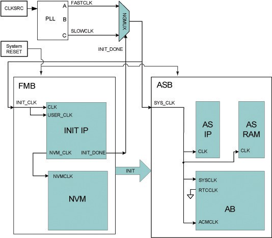
You can use a PLL to create the two clock frequencies, FASTCLK and SLOWCLK. The GLA and GLC outputs of the PLL are then routed through an NGMUX to enable clock switching. During system initialization, SLOWCLK is used to drive both the FMB and ASB subsystems. After initialization completes, the clock switches to the higher‑frequency FASTCLK, as shown in the figure.
This clock‑switching mechanism is required to satisfy the silicon frequency limitation of the Analog Configuration multiplexer (ACM) interface. Once ACM initialization is complete, the ACMCLK may be driven at a frequency greater than 10 MHz. During simulation, the AB library macro may issue warning messages indicating that the ACM clock exceeds 10 MHz. These warnings can be safely ignored after initialization, provided that the ACM interface is not accessed while the clock frequency exceeds 10 MHz.
If these simulation warnings are not desired, ACMCLK can be tied directly to SLOWCLK. To export the ACM clock, open the Analog System Builder Advanced Options dialog box dialog box and enable the ACM clock option. When exported, an ACMCLK port is added to the Analog System, allowing the GLC output of the PLL to be connected directly to ACMCLK, which eliminates the simulation warnings.
The INIT_DONE signal from the Flash Memory Block is used to control the NGMUX selection between initialization and normal operation clocks.
In the Figure 2-13 figure, AS IP and AS RAM represent the Analog System soft IP modules and their associated RAM blocks.