
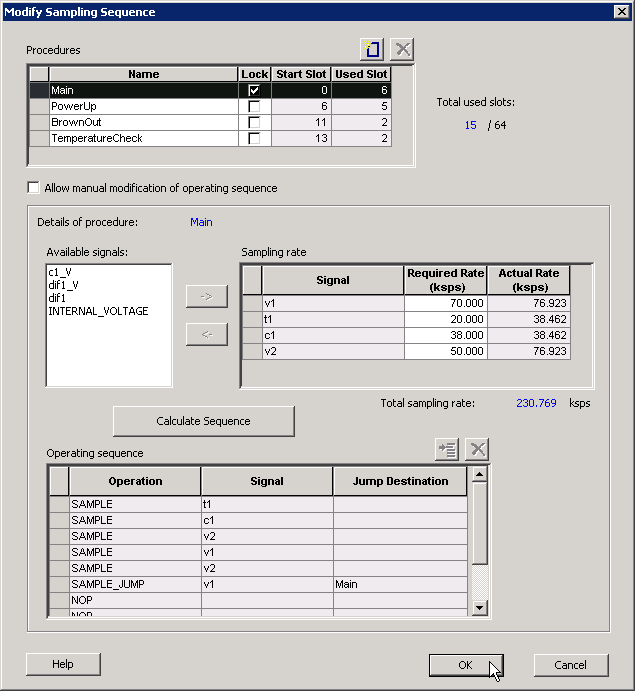
2.1.4 Modify Sampling Sequence
This section explains how to define, calculate, and manage sampling sequences and procedures in the Analog System Builder.
There can be up to 30 analog input channels, depending on the device, but only one ADC is available. Therefore, the channels must be sequenced in the desired sampling order. You have a total of 64 time slots available for sequencing. Besides sampling operations, the sequencer can also perform non-sampling operations, such as calibration or power-down.
The application requirements determine the sampling sequence. The sampling sequence specifies the Analog System sampling order. For example, the sequence can be configured to sample voltage channel 1 continuously, or to sample voltage channel 1, voltage channel 2, and temperature channel 1 in a repeating pattern. In all cases, the ASSC drives the ADC control signals to sample channels according to the specified sequence.
- Procedures
-
Procedures are logical groupings of sampling sequences. Each procedure is intended to operate independently of other procedures.
A common use model for multiple procedures is a system that requires one set of samples during system power‑up and a different set after power‑up. For example, during power‑up, the system may monitor voltage channels 1 and 2. After a stable voltage level is reached, a different set of analog channels may be monitored.
In this scenario, two procedures can be defined:
- A PowerUp procedure that samples voltage channels 1 and 2 repeatedly.
- A SteadyState procedure that monitors the remaining analog inputs once stability is achieved.
The logic required to determine when to trigger a different procedure must be implemented by the user through the external sequencer control interface. The external trigger interface is exported only when more than one procedure is defined. For more information, refer to the External Trigger Signals in Analog System Builder section.
The ability to define multiple procedures that loop independently enables these types of operating models.
The system always includes a default main procedure. This procedure cannot be deleted or unlocked. It always starts at slot 0 and is executed automatically after reset.
The following fields are used to define a procedure:
- Name: Specifies the procedure name.
- Lock: Locks the starting slot of the procedure. This option is useful when an existing design already includes logic to trigger a specific procedure. When selected, the Start Slot field is editable; otherwise, it is read‑only and the software assigns the starting slot automatically.
- Start Slot: Starting slot number for the procedure. This value must be driven on the ASSC_SEQUIN port to trigger execution of the procedure.
- Used Slots: Number of physical time slots used by the procedure. The sequencer supports a maximum of 64 slots.
- Total Used Slots: Total number of slots used by all procedures. If this value exceeds 64, it is displayed in red to indicate a violation.
After entering procedure parameters, click Add Procedure to create a new procedure or Delete Procedure to remove an existing one. The Operating Sequence and Sampling Rate grids update when a different procedure is selected.
- Sampling Rate
The sampling sequence includes an automatic sequence calculation feature. A checkbox labeled Allow manual modification of operating sequence enables or disables this feature.
When Allow manual modification of operating sequence is unchecked, sampling‑rate requirements can be specified on a per‑channel basis. Channels must be selected from the list of available signals and added to or removed from the grid. After a channel is added, a required sampling rate (in kilo‑samples per second) can be specified. Clicking Calculate Sequence causes the software to compute a sampling sequence that most closely meets the specified requirements.
When Allow manual modification of operating sequence is checked, this section displays only the actual sampling rate for each channel. Adding or removing channels from the operating sequence automatically updates the reported sampling rate for the selected procedure. Because procedures operate independently, sampling‑rate calculations are performed separately for each procedure.
The grid displays the actual sampling rate for each channel, and the Total Sampling Rate field indicates the combined sampling rate of all channels for the selected procedure.
- Operating Sequence
The operating sequence defines the sequence of operations executed for a selected procedure. The supported operations are:
- SAMPLE: Samples a configured channel and proceeds to the next slot.
- SAMPLE_JUMP: Samples a configured channel and jumps to the start of a specified procedure.
- CALIBRATE: Performs a full calibration of the ADC (requires 3840 ADC clock cycles) and proceeds to the next slot.
- CALIBRATE_JUMP: Performs a full calibration and jumps to the start of a specified procedure.
- JUMP: Jumps directly to the start of a specified procedure.
- POWERDOWN: Powers down the ADC. After a power‑down operation, a calibration operation is required before sampling can resume.
- STOP: Stops the sequencer. An external trigger is required to restart operation.
- NOP: Performs no operation and proceeds to the next slot. NOP operations within a sequence consume a time slot; NOP operations after the final functional slot do not.
Each operating sequence must end with a terminating operation. Valid terminating operations include SAMPLE_JUMP, CALIBRATE_JUMP, JUMP, POWERDOWN, and STOP.
Slots can be inserted or removed using the Add Slot and Delete Slot buttons.
- Calculate Sequence
When Calculate Sequence is selected, the Analog System Builder generates a sampling sequence that attempts to meet the sampling‑rate requirements specified for the procedure.
An additional INTERNAL_VOLTAGE peripheral with an acquisition and hold time of 5 µs may be added to satisfy strobe requirements.
The sequence calculation attempts to balance sampling rates across all channels by minimizing the difference between the required and actual sampling rates.