
2.2.2 Differential Voltage Monitor
The Differential Voltage Monitor uses the same internal components as the Current Monitor.
In Fusion devices, the Differential Voltage Monitor measures the differential voltage between a pair of Voltage and Current input channels. This peripheral requires two channels—one of type V and one of type C—and these channels must be mapped to adjacent package pins.
The differential amplifier gain for the Differential Voltage Monitor is 10×. The differential amplifier measures the voltage difference between the two inputs, with a maximum differential of 256 mV when using an internal reference voltage of 2.56 V.
The Voltage channel in the channel pair can also be used as a Voltage Monitor to measure the absolute voltage applied to the Voltage input.
For information on digital filtering factor, acquisition time, and comparison‑flag specifications, see Configuring Current, Voltage, and Temp peripherals section.
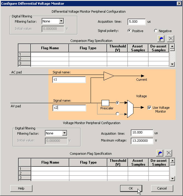
- Differential Voltage Monitor Configuration Options
- Polarity: Specifies the measurement polarity as positive or negative. The associated Voltage values must match the selected polarity. ASB issues a warning if the Voltage values do not match the selected polarity. When negative polarity is selected, the prescaler option for the associated Voltage Monitor defaults to the prescaler path
- Maximum voltage: Specifies the maximum anticipated voltage measured by the Voltage Monitor pad associated with this peripheral. The valid range is –10.5 V to +16 V (the voltage range is not bipolar). The ADC measures voltages in the range 0 V to VREF. When using the internal reference, VREF = 2.56 V. ASB automatically configures the prescaler in the analog block to maximize the available voltage range for this peripheral.