
2.2.7 Real Time Counter
The on-chip crystal oscillator circuit works with an off-chip crystal to generate a high-precision clock. It has an accuracy of 100 ppm (0.01%) and is capable of providing system clocks for Fusion peripherals and the other system clock networks, both on- and off-chip. When combined with the on-chip CCC/PLL blocks, a wide range of clock frequencies can be created to support various design requirements.
The Real Time Counter inside the Analog Block has the following features:
- The MATCH signal on the output of the system asserts when the value in the counter matches the value specified in the match register. Also, there is an optional output RTCPSMMATCH that is triggered on match. The RTCPSMMATCH signal must be connected to the RTCPSM macro so that the Voltage Regulator activates when the Match signal is asserted.
- If you use the RTC, RTCCLK must be driven by the External Crystal Oscillator driving the Fusion device and the mode of the Crystal oscillator must be controlled by the RTC.
- Displays two different views: Alarm or Custom view. The alarm time specified in the RTC dialog relates to the deassertion of one RTCMATCH signal to the reassertion of the signal.
For more information on connectivity, see the Designing with Analog System Builder section.
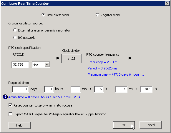
- Time Alarm View
The Time Alarm View enables time‑based configuration of the RTC. The desired time can be entered in days, hours, minutes, seconds, milliseconds, and microseconds. The granularity of achievable time values depends on the configured RTC clock frequency. The actual time value used by the hardware is displayed in blue.
- Maximum Time: Displays the total representable time supported by the 40‑bit RTC counter at the selected clock frequency. In this mode, the RTC initial value is automatically set to 0 and cannot be modified.
ASB displays both the requested time and the actual achievable time based on the RTC clock frequency.
For example, when the clock frequency is 32.768 kHz, each clock tick is approximately 3.9 ms. If a required time of 4 ms and 100 µs is entered, ASB selects the next achievable value, which is 7.8 ms, and displays it as the actual time.
- Register View
- Initial Value: Specifies the starting value of the RTC counter. The default value is 0. This value can be entered as a 40‑bit binary or 10‑digit hexadecimal number.
- Match Register Value: Specifies the value that causes the MATCH signal to assert. This value can be entered as a 40‑bit binary or 10‑digit hexadecimal number.
- Crystal Oscillator Source
The RTC supports the following crystal oscillator configurations:
- External crystal or ceramic resonator: Configures the oscillator to operate with an external crystal or ceramic resonator.
- RC network: Configures the oscillator to operate with an external resistor‑capacitor network.
- RTC Clock Specification
- RTCCLK: Specifies the frequency of the CLKOUT signal from the crystal oscillator.
Based on the RTCCLK frequency and the selected oscillator mode, ASB automatically configures the oscillator parameters as shown in the following table:
| Mode | Recommended Capacitor | Frequency Range (MHz) |
|---|---|---|
| LOW_GAIN | 100 pF | 0.032 – 0.20 |
| MEDIUM_GAIN | 100 pF | 0.21 – 2.0 |
| HIGH_GAIN | 15 pF | 2.1 – 20.0 |
The RTCCLK signal is divided internally by 128 to generate the clock used by the RTC counter. The resulting frequency and period are displayed in blue in the dialog box.
- Reset Count to Zero When Match Occurs: Resets the RTC counter to zero after a match event. This option can be disabled for applications that measure elapsed time.
- Export Match Signal for Voltage Regulator Power Supply Monitor: Asserts RTCPSMMATCH to activate the Voltage Regulator Power Supply Monitor (VRPSM).
If dynamic updates to the RTC match or counter registers are required during operation, enable ASB Advanced Options and select the ACM Bus option. For more information, see the ASB Advanced Options - ACM Bus section.