
2.2.9.1 Use Prescaler or Direct Analog
Each analog channel includes a prescaler circuit that can scale the input signal to a level supported by the ADC. Using the prescaler imposes additional requirements on the acquisition time of the peripheral. The two radio buttons adjacent to the multiplexer select whether the Voltage Monitor uses the prescaler path or the direct analog path.
If the input voltage is less than the ADC reference voltage and high accuracy is critical for the application, select the direct analog path. The prescaler circuit can introduce potential gain or offset errors. If resolution is more important than absolute accuracy for input voltage ranges below the ADC reference voltage, select the prescaler path.
The prescaler logic in the AB has a maximum settling time of 10 µs. This settling time is application‑dependent and must be accounted for through the acquisition and hold time configured for each channel. A recommended default value is automatically inserted by the ASB when configuring a new Voltage Monitor; however, this value may be reduced at the expense of reduced sampling accuracy.
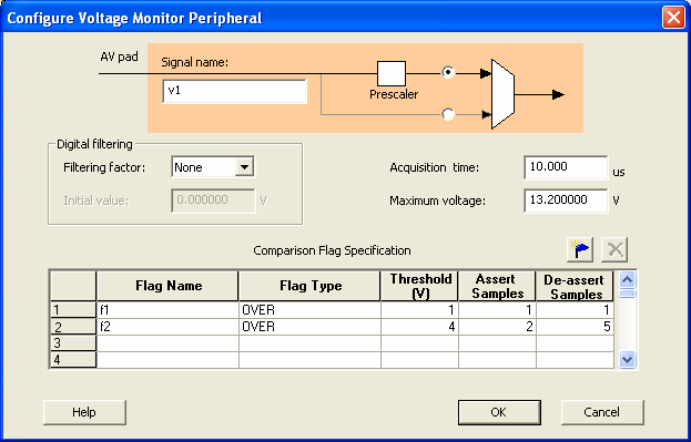
- Maximum Voltage
Specifies the maximum anticipated voltage measured by the Voltage Monitor peripheral pad. The valid range is –10.5V to +16V (the voltage range is not bipolar). The ADC is capable of measuring voltages in the range 0V to VREF. When using the internal voltage reference, VREF = 2.56V. ASB automatically configures the prescaler in the analog block to maximize the available voltage range for this peripheral.
Setting the Maximum Voltage to a negative value requires that the input voltage driving this signal be negative. Threshold‑flag evaluation for negative voltages is performed on a mathematical scale.
For example, if an OVER –3V flag is configured, the flag asserts when the input voltage is –1V or –2V (up to the threshold value) and deasserts when the voltage reaches –4V, –5V, and so on.