2.2.7.1 RTC Signals
All signals are active high.
| Name | Direction | Description |
|---|---|---|
| RTCCLK | Input | RTC clock input. Must be driven by the XTLOUT output of the XTLOSC macro. |
| RTCXTLSEL | Output | Crystal oscillator select signal. Must be connected to XTLSEL on the XTLOSC macro. |
| RTCXTLMODE[1:0] | Output | Crystal oscillator mode select. Must be connected to RTCXTLMODE on the XTLOSC macro. |
| RTCMATCH | Output | Match signal asserted when the RTC counter reaches the programmed match value. |
| RTCPSMMATCH | Output | Match signal asserted when the RTC counter reaches the programmed match value. This signal must be connected to RTCMATCH of the VRPSM macro. It is exposed only when Export Match signal for Voltage Regulator Power Supply Monitor is enabled. |
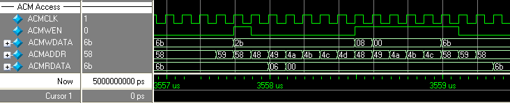
The following figure illustrates access to the Analog Configuration multiplexer (ACM) for RTC register values. In the sequence shown, the RTC counter is first disabled, the RTC match register is read, the match register is then overwritten with a new value, and finally the RTC is re‑enabled.