
1.2.3 Analog System Builder Main Window
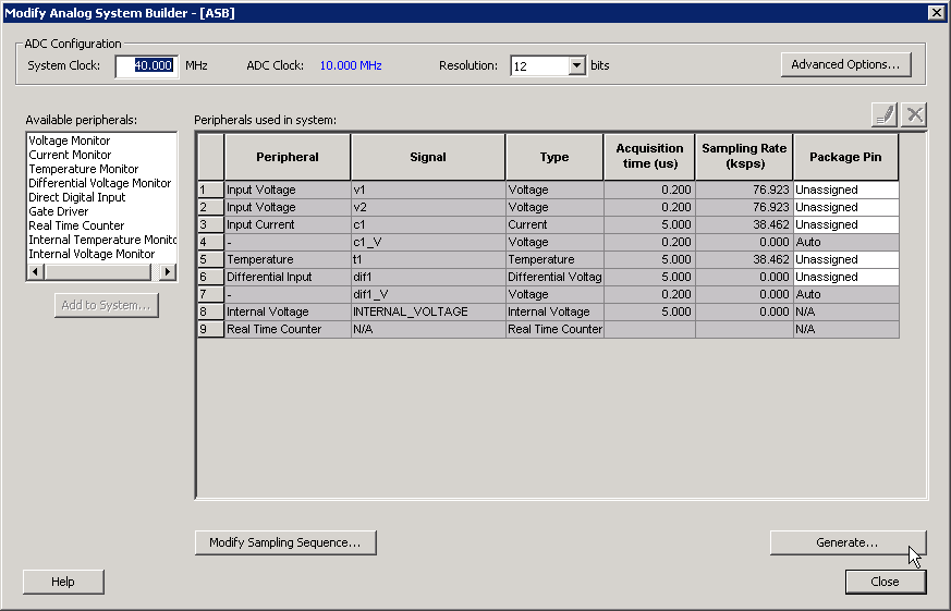
The Analog System Builder main window enables you to create and configure your analog system (as shown in the figure below).
The number of peripherals you can add to the system is limited by the size of your device.
The ADC Clock is the frequency at which analog to digital conversions occur. The ASB evaluates the required acquisition times for all peripherals and the system frequency to compute the maximum possible ADC clock frequency. Only certain divider factors exist to create the ADC Clock; because of this and peripheral acquisition times, certain system frequencies result in a faster ADC Clock. For more information on Analog System clocks, refer to the Designing with Analog System Builder section .
You can select the resolution of the ADC (8-, 10-, and 12-bit modes). Selecting the resolution affects the meaningful bits read from the ADCRESULT port, ASSC_RAM, and SMEV_RAM.
- In 12-bit mode, the ADC uses 11:0
- In 10-bit mode, the ADC uses 11:2; 1:0 are grounded
- In 8-bit mode, the ADC uses 11:4; 3:0 are grounded
Click Advanced Options to set your Analog System configuration.
Available Peripherals lists all the analog peripherals you can add to your design. As you add peripherals, some resources are exhausted. If you exceed the resource limit, the ASB returns a warning during file generation. If you want to add additional peripherals, select a larger device, or remove some existing peripherals from your design.
The Peripherals used in system grid lists specific information about each peripheral, including the following:
- Peripheral - The type of the peripheral (such as Voltage Monitor, Temp. Monitor, etc.).
- Signal - Name you specified for the signal of your service in the service configuration dialog box.
- Type - Identifies channel type for the service.
- Acquisition Time - The required acquisition time for a given input channel. ASB takes the required acquisition times for all peripherals and computes the maximum possible ADC clock frequency and the number of ADC clocks per sample and per peripheral.
- Sampling Rate (in s) - This field only displays the sampling rate for the channels specified in the “Main” procedure. For more information on setting your sampling sequence, see the Modify Sampling Sequence section . See the Sampling Rate in Analog System Builder section for more information on how the sampling rate is calculated.
- Package Pin - ASB automatically assigns a package pin for each channel in each peripheral added to the system. However, if you require a specific channel for a certain package pin (if you have board layout issues), you can choose a specific pin for that channel.
- Real Time Counter - You can configure the Real Time Counter so that it functions as a chronometer, allowing it to generate periodic alarms in conjunction with other peripherals (such as the Voltage monitor, etc.).
- Modify Sampling Sequence - This displays the Sample Sequencer. Since there are thirty analog input channels but only one ADC, the channels must be sequenced in the order in which they are to be sampled.
If the Analog System resources you build exceed the total system resources available for your device, ASB issues a warning. You cannot generate a system that exceeds your total system resources. The Analog System Builder also generates a warning if you have a port name conflict between two or more services. You cannot generate a system with port name conflicts.
When you click Generate, ASB creates HDL source files, memory (MEM) files, configuration files, and log files. They all appear in your project folder under the <core_name> directory. Do not modify any of these generated files or store additional files in this folder. This folder will be recreated every time you overwrite the core.