
1.2.4 Modify Sampling Sequence
Since there are 30 input channels (depending on the device) but only one ADC, the channels must be sequenced in their desired order. There are 64 time slots available for sequencing. You can also run non-sampling operations in the sequencer (such as calibration or powerdown).
Your application requirements dictate the sampling sequence.
The sampling sequence specifies the Analog System’s sampling order. For example, the sequence may be specified to sample "voltage channel 1" continuously, or it can be specified to sample "voltage channel 1", "voltage channel 2", "temperature channel 1", and repeat. In either case, the Sample Sequence Controller drives the ADC signals to sample the channels in the specified sequence.
The sampling sequence has an Automatic Sequence calculation feature. A checkbox to enable or disable this feature is labeled “Allow manual modification of operating sequence”. When unchecked, sampling rate requirements may be entered for channels and software attempts to calculate a sequence that meets the rate requirements and satisfies the ordering rules. When unchecked the operating sequence may be specified manually.
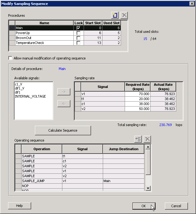
Procedures
Procedures are a logical composition of sequences. Each procedure is intended to be completely independent of another procedure.
An example use-model for multiple procedures is a system that requires one set of samples during system power-up, and another set after power-up. For example, upon power-up the system needs voltage channels 1 and 2 monitored. Then after a certain event, such as reaching a stable voltage level, a different set of analog channels need to be monitored.
- A ‘Powerup’ procedure that samples voltage 1, voltage 2, and repeat.
- A ‘SteadyState’ procedure that continually monitors the rest of the analog inputs once it has been determined that a steady and stable voltage level has been reached.
The intelligence to determine when to trigger another procedure must be performed by the user through the external sequencer control interface. The External Trigger interface is only exported if there is more than one procedure.
The ability to have multiple procedures that can continually loop upon themselves allows for these types of use-models.
The system defaults to having a single “Main” procedure that can not be deleted or unlocked. It always starts at slot 0 and will always be the procedure that is executed upon reset.
- Name – Enter a name for your procedure
- Lock – Lock the starting slot of the procedure, this is useful if you have an existing design that already has logic to trigger a procedure. If lock is checked, the start slot field is modifiable otherwise it is read-only and software will assign a starting slot for the procedure.
- Start Slot – This is the starting slot number for this procedure. This number is required to trigger this procedure to start executing. Drive this value into the ASSC_SEQIN port.
- Used Slots – Indicates the number of physical slots used up by this procedure. Recall that the sequencer only supports up to a total of 64 slots.
- Total Used Slots – The total number of slots used by all the procedures, if it exceeds 64 it will turn red indicating that a violation has occurred.
Input your procedure values and click Add Procedure to create a new procedure. Click Delete Procedure to delete a procedure.
The Operating Sequence and Sampling Rate grids change when you select a procedure.
Sampling Rate
When Allow manual modification of operating sequence is unchecked, you can specify your rate requirements per channel here. The channel must selected in the list of available signals and added / removed from the grid. After it has been added to the grid, a required sampling rate (in kilosamples per second) may be specified for that channel. Clicking Calculate Sequence initiates software to calculate a sequence that most closely meets the your requirement(s).
When Allow manual modification of operating sequence is checked, this section is used only to report the sampling rate of the channels. By adding and removing channels to the operating sequence, this grid automatically updates with the actual sample rate for that channel for this procedure. Recall that procedures are completely independent, so the sample rate calculation is performed per procedure and include any of the other procedures.
The actual sampling rate for each channel is displayed in this grid. The total sampling rate indicates the total sampling rate of all channels for the selected procedure.
Operating Sequence
The operating sequence for a selected procedure. The supported operations are:
- SAMPLE - Sample a channel that is configured in the system and proceed to the next slot
- SAMPLE_JUMP – Sample a channel that is configured in the system and jump to the start of the specified procedure
- CALIBRATE – Perform a full calibration of the ADC (this requires 3840 ADC Clocks to complete) and proceed to the next slot
- CALIBRATE_JUMP – Perform a full calibration and jump to the start of the specified procedure
- JUMP – Jump to the start of the specified procedure
- POWERDOWN – Perform a powerdown operation on the ADC; after a powerdown is initiated, a calibration operation is required to resume sampling
- STOP – Stop the sequencer; an external trigger is required to re-start the sequencer
- NOP – No operation is performed and proceed to the next slot. NOP’s in the middle of a sequence use up a time slot, but NOP’s after the end of the last functional slot do not.
- Terminating slots: Each operating sequence must end with a terminating operation. A terminating operation is a SAMPLE_JUMP, CALIBRATE_JUMP, JUMP, POWERDOWN, or STOP.
Slots can be inserted or deleted with the Add Slot button or Delete Slot button, respectively.
Calculate Sequence
The ASB creates a sampling sequence that attempts to meet the sampling rate requirement specified for the procedure.
An additional INTERNAL_VOLTAGE peripheral with an acquisition and hold time of 5 s may be added to your system to satisfy strobe requirements.
The sequence calculation attempts to fairly balance the sampling rate among the signals by reducing the difference between the actual and required rate.