20.2.20 Importing a VCD File
The Value Change Dump (VCD) file is a simulation file. The format of this file is specified in the IEEE 1364 standard.
You can configure the Project Manager to automatically generate VCD files using ModelSim. You can also generate a VCD file with a ModelSim simulator using the following commands:
vcd file example.vcd
vcd add -r /testbench/<top>_0/* run 1 us
vcd flush
This example creates a VCD file example.vcd, adds all signals recursively, runs the simulation for one micro second, and quits. You must quit ModelSim in order to get an accurate result from SmartPower.
If you have not yet completed the layout of the design, the design software guides you through place-and-route so that you can import the VCD file. In order to successfully annotate your VCD values to the design, Designer must complete place-and-route even if you generated your VCD file using timing simulation (pre-layout).
SmartPower has been validated with VCD files generated by ModelSim. However, you may use any Verilog/VHDL simulator that offers a VCD dump feature.
Refer to the user manual of your simulation tool for more information on how to generate a VCD file.
To import a VCD file:
- From the Simulation menu, select Import VCD File. This opens the Import VCD Options dialog box.
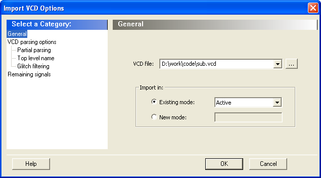
- Select the VCD file you want to import and select a mode to import it in, or click New Mode and enter a mode name.
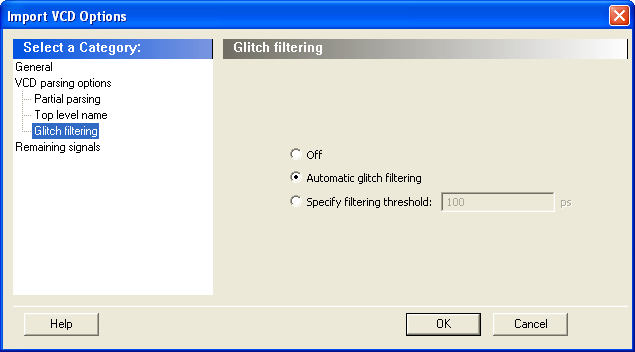
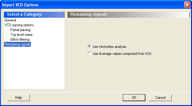
- Select the options you want to specify:
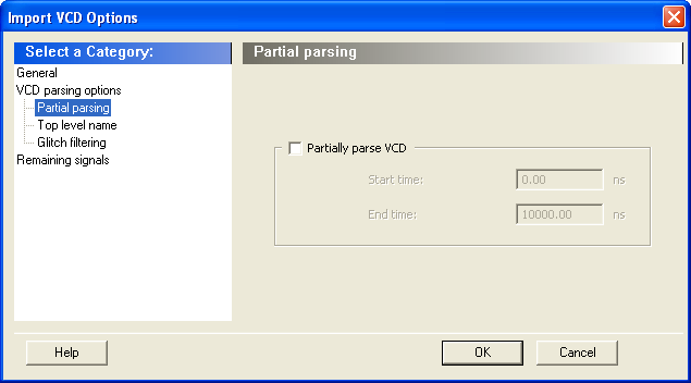
Partial Parsing: Specify the Start and End Times to partially parse the VCD file. This option can be used for large VCD files.
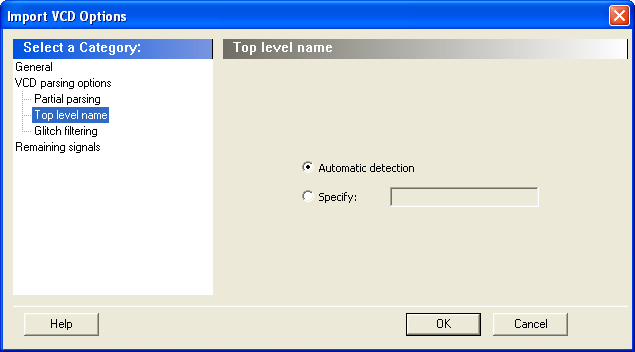
Top-Level Name: This option enables you to select how the top-level name is specified. The Top Level Name is the instance name of your design instantiated in the simulation testbench.
- Click OK.
- When the vcd file is successfully imported, the file appears in the Modes and Scenarios toolbar, under the imported mode. The following messages appear in the Designer Log window:
Info:
VCD:34 glitch(es) filtered with 1000 ps threshold
The message above reports the number of glitches that have been filtered by the VCD reader.
Info:
VCD: Annotation Statistics
Percentage of Annotated Pins:100.00 % Percentage of Unannotated Pins:0.00 %
Percentage of Annotated Pins with Zero Frequency: 25.99 %
If the percentage of annotated pins is less than 50.00%, a warning message will be generated.
If the percentage of annotated pins is low, you may want to verify that signals at all levels of hierarchy were added recursively (for example using vcd add –r in ModelSim).
If you simulate a pre-synthesis netlist or a post-synthesis RTL netlist, it is possible to get a low percentage of annotated pins. This happens because not all logic elements are in the pre-synthesis netlist and the post-synthesis RTL netlist. For accurate power estimation, it is best to run post-layout simulation with a back-annotated netlist.
If you want to see exactly which pins are not annotated, open the SmartPower Frequencies tab. If your file was imported successfully, you will see a list of pins with annotated individual frequencies displayed with VCD Import as a source. The unannotated pins are displayed with Default Estimation as source. If your design has enable pins, open the SmartPower Probabilities tab.
After finishing the import VCD process, you can now create a custom mode based on the active mode. This custom mode will inherit all the clock and toggle frequencies of the active mode that have just been set through the VCD import. This final step is optional. It gives you the flexibility to modify the active mode frequencies while saving the VCD scenario in SmartPower. Refer to Custom operating modes for more details.
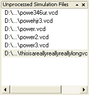
If you generated the VCD file from Project Manager and if you are using Designer from Libero IDE, the list of generated VCD files appear in the unprocessed VCD file list. To import the VCD file, right-click and select Import VCD File.