10.4.13.3.3 Manual Buffering
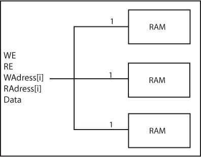
The Manual Buffering figure shows how manual buffering is executed. A fan-in of one (1) is enforced on all signals fanning out to more than one RAM cell. If these signals were broadcast to all RAM cells, very slow routing resources (long freeways) would be required to route the signals impacting the RAM performance.
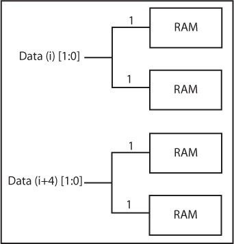
Manual buffering should only be used if the expected performance is not realized using the automatic buffering scheme, or if you know ahead of time that you need to use this scheme to meet your timing goals. In this architecture, the idea is not to buffer the signals internally but rather give some kind of access to the RAM core internal signals. Then, you must buffer the signals outside the core and either use traditional buffers or duplicate the logic that drives these signals externally. If you choose manual buffering, the WE, RE, Waddress(i), RAddress(i), and Data[i] signals become busses external to the core. For all these signals, the bus width is equal to the number of RAM cells (used to build a given configuration) driven by each signal. The Manual Buffering following figure illustrates the manual buffering architecture for a 96x8 RAM configuration, built of three 32x8 configured RAM cells. In this configuration, the WE, RE, WAddress and RAddress signals drive all RAM cells simultaneously. The Manual Buffering for the Data Bus shows a 128x8 RAM configuration, built using four 64x4 configured RAM cells. In that configuration, the 8-bit data bus is split into two completely independent 4-bit data busses.