
10.1.9 Linear Binary Counters
A Linear Binary Counter is a sequential logic blocks that increment or decrement binary values in a linear sequence on each clock cycle, commonly used for counting and timing applications.
Supported Families
ProASICPLUS®
- ProASIC
- Axcelerator®
- MX
- eX
- SX/SX-A
Related Topics
Key Features
- Parameterized word length
- Up, down and up/down architectures
- Asynchronous clear
- Asynchronous preset (available only for Flash devices)
- Synchronous counter load
- Synchronous count enable
- Terminal count flag (not available for Axcelerator)
- Multiple gate-level implementations (area/speed tradeoffs)
- Behavioral simulation RTL in VHDL and Verilog
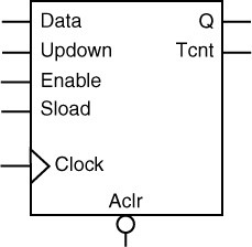
Binary counters are general purpose UP, DOWN or UP/DOWN (direction) counters.
When the count value equals 2width-1, the signal Tcnt (terminal count), if used, is asserted high.
The counters are WIDTH bits wide and have 2width states from “000…0” to “111…1”. The counters are clocked on the rising (RISE) or falling (FALL) edge of the clock signal Clock (CLK_EDGE).
The Clear signal (CLR_POLARITY), active low or high, provides an asynchronous reset of the counter to “000…0”. You may choose to not implement the reset function. If you do not use the Clear signal, Microchip recommends that you use Sload to set the initial counter contents to a known value.
In the case of an Up/Down counter, the Updown signal controls whether the counter counts up (Updown = 1) or down (Updown = 0).
The counter could be loaded with Data. The Sload signal (LD_POLARITY), active high or low, provides a synchronous load operation with respect to the clock signal Clock. You can choose to not implement this function. If you do not use the Sload signal, Microchip recommends that you use Clear to set the initial counter contents to a known value.
The counters have a count enable signal Enable (EN_POLARITY). Enable can be active high or low. When Enable is not active, the counter is disabled and the internal state is unchanged.