
12.4.4.1 Asynchronous/Synchronous Mode Context
In Asynchronous mode, the Baud Rate (BR) clock is generated by dividing the input reference clock's frequency (APB_0_CLK for MMUART_0 and APB_1_CLK for MMUART_1) by 16 and the integer plus fractional divisor value, as shown in the following equation.
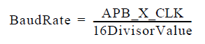
Divisor Value = Integer Value (DMR + DLR registers) plus Fractional Value (DFR/64).
In the Synchronous Master mode, the baud rate clock is generated by dividing the input reference clock's frequency (APB_0_CLK for MMUART_0 and APB_1_CLK for MMUART_1) by 2 and the integer divisor value, as shown in the following equation.
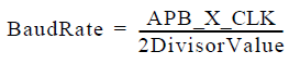
DivisorValue = Integer Value (DMR + DLR registers).
In the Synchronous Slave mode, the baud rate clock is generated directly from the input clock, and as such the divisor registers are not used.
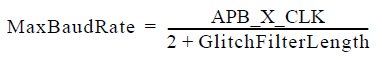
The Glitch Filter Length (GLR) can be configured by setting the bits in glitch filter register (Table 12-25).