5.54 Quad Input Page Program
The Quad Input Page Program instruction programs up to 256 bytes of data into memory. Before initiating the operation, the selected page address must be in the erased state (FFH). If the instruction is applied to a protected memory region, the operation is ignored. The Quad Input Page Program instruction requires the IOC bit in Status Register 2 to be set to 1 before execution. The Write Enable (WREN) instruction must also be executed prior to issuing the command.
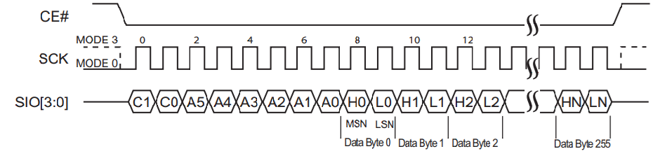
To execute a Quad Input Page Program operation in SPI mode, the host drives CE# low, issues the command cycle (32H), and transmits three or four address cycles in SPI mode, followed by the data to be programmed using SIO[3:0]. The host then drives CE# high. The programmed data length must be between 1 and 256 bytes in whole-byte increments. The command cycle is eight clocks long, while the address and data cycles are each two clocks long, with the Most Significant bit transmitted first. Completion of the internally timed write operation can be verified by polling the Busy bit in Status Register 1 or by waiting for the specified TPP interval. Refer to Figure 5-48 for the SPI-mode sequence.
To execute a Quad Input Page Program operation in QPI mode, the host drives CE# low, issues the command cycle (32H), and transmits three or four address cycles followed by the data using SIO[3:0], then drives CE# high. The programmed data length must be between 1 and 256 bytes in whole-byte increments. The command cycle is eight clocks long, and the address and data cycles are each two clocks long, with the Most Significant bit transmitted first. Completion of the internally timed write operation can be verified by polling the Busy bit in Status Register 1 or by waiting for the specified TPP interval. Refer to Figure 5-49 for the QPI-mode sequence.