
14.8.150 IODFEP
This component is supported by ACT 3 families.
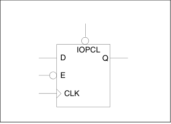
- Function: D-Type Flip-Flop with active low Enable and Preset
- Input: IOPCL, D, E, CLK
- Output: Q
| IOPCL | E | CLK | Qn+1 |
|---|---|---|---|
| 0 | X | X | 1 |
| 1 | 1 | X | Q |
| 1 | 0 | ↑ | D |
Note:
The CLK pin must be driven by the IOCLKBUF macro.
Note:
The IOPCL pin must be driven by the IOPCLBUF macro.
Note:
Uses an I/O module.