
14.8.231 DLM8B
This component is supported by ACT 3 family.
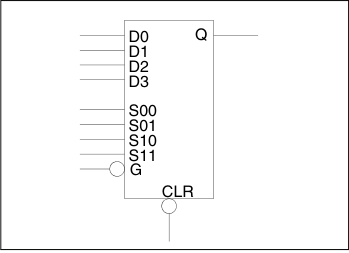
- Function: D-Type Latch with 4-input Multiplexed Data and active low Clear and Clock
- Input: D0, D1, D2, D3, S00, S01, S10, S11, G, CLR
- Output: Q
| CLR | S11 | S10 | S01 | S00 | G | Qn+1 |
|---|---|---|---|---|---|---|
| 0 | X | X | X | X | X | 0 |
| 1 | X | X | X | X | 1 | Q |
| 1 | 0 | 0 | 0 | X | 0 | D0 |
| 1 | 0 | 0 | X | 0 | 0 | D0 |
| 1 | 0 | 0 | 1 | 1 | 0 | D1 |
| 1 | 1 | X | 0 | X | 0 | D2 |
| 1 | X | 1 | 0 | X | 0 | D2 |
| 1 | 1 | X | X | 0 | 0 | D2 |
| 1 | X | 1 | X | 0 | 0 | D2 |
| 1 | 1 | X | 1 | 1 | 0 | D3 |
| 1 | X | 1 | 1 | 1 | 0 | D3 |
| Family | Seq | Comb |
|---|---|---|
| ACT 3 | 1 | — |
Note: The DLM8B macro represents the full ACT 3 S-Module.
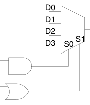
Note: The DLM8B select-line interconnection schematic describes the interconnections of the select lines.